| ID |
Date |
Author |
Status |
Type |
Category |
Location |
Title |
|
146
|
Wed Sep 7 18:58:03 2022 |
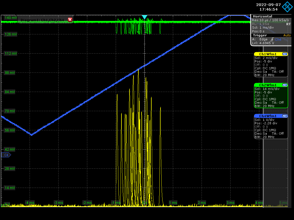
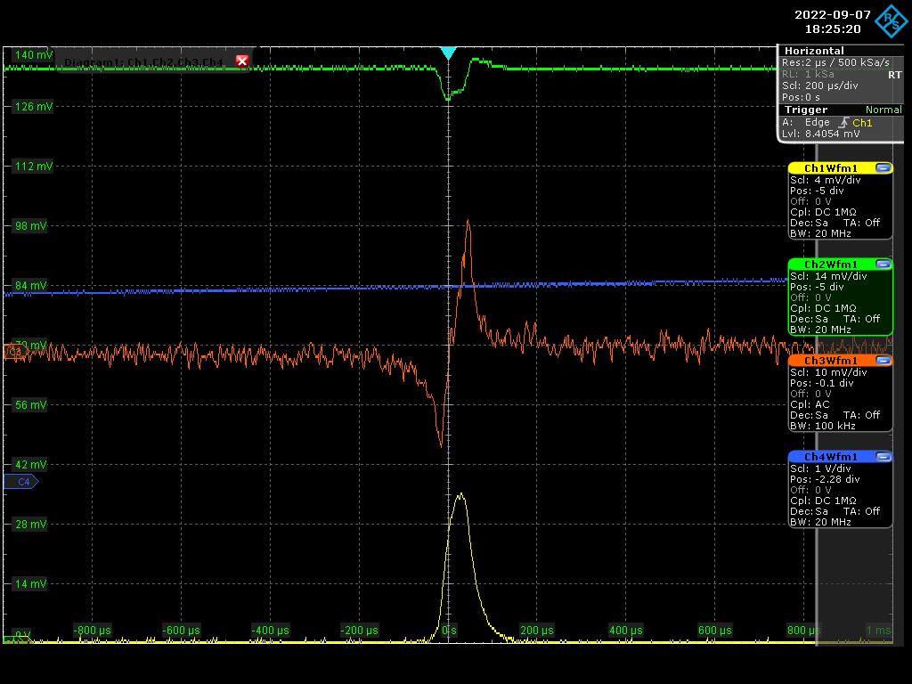
Manar Amer | Fixed | report | lasers and optics | Optical room | Locking Amplifier with Cavity | Today we managed to observe the fundamental mode and stabilize the scan on it until we improved the alignment enough.
We see some coupling, but it is very week < 5% , We improved the alignment and the polarization, but there is still no explanation to why it is very low.
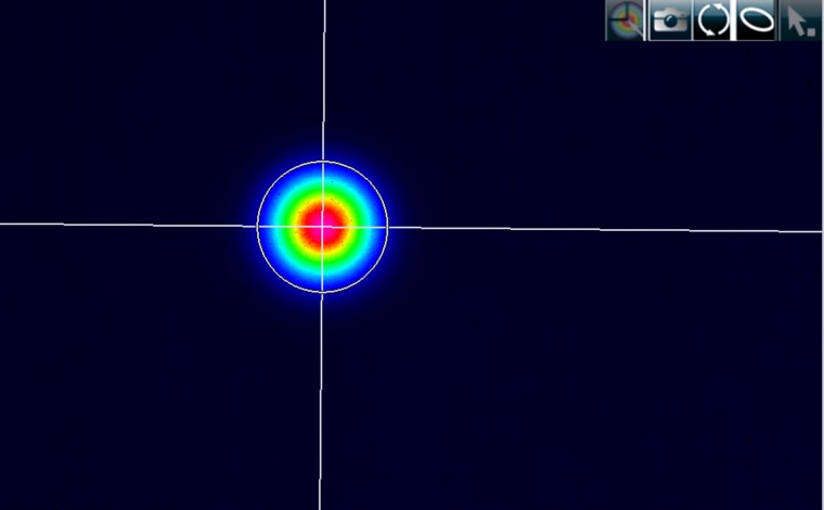
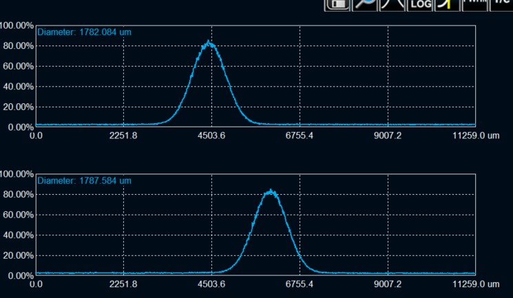
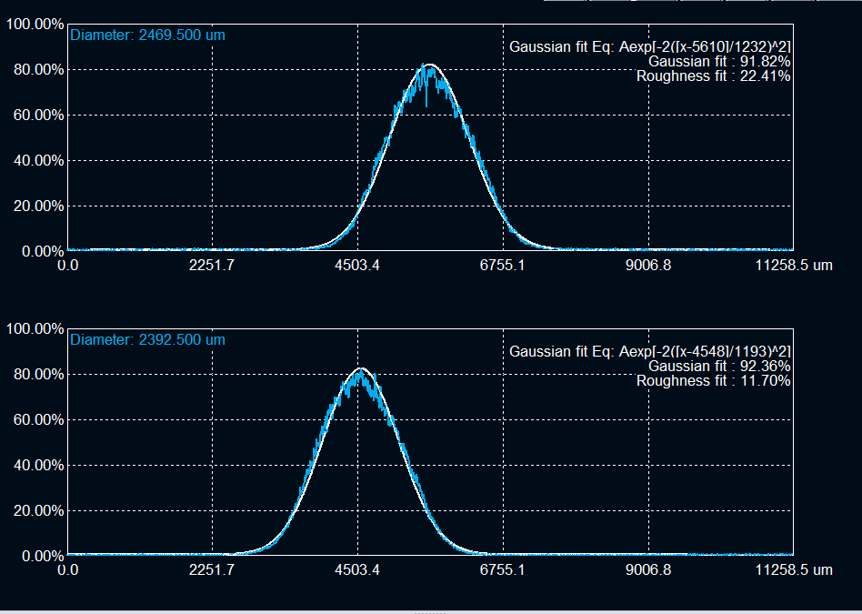
The mode shape is circular with radius = 0.89 mm at transmission point, ~ 40 cm from circular mirror.
One EOM was installed along the injection into the amplifier, we saw a drop in the power measured by the first stage monitor from ~ 8.2 mW to 7.2 mW
we improved the injection up to 7.6 mW, but it still fluctuates a lot. We need to be careful about it.
The error signal looks clean, but it is very week which is due to the weak coupling.
|
| Attachment 1: 20220907_00mode.jpg
|  |
| Attachment 2: 20220907_00mode_diameter.jpg
|  |
| Attachment 3: Screenshot_2022-09-07_0_174654.png
|  |
| Attachment 4: Screenshot_2022-09-07_2_182520.png
|  |
|
147
|
Thu Sep 8 11:16:40 2022 |
Manar Amer | Fixed | report | lasers and optics | Optical room | Locking Amplifier with Cavity | Today, we played on the CEP but using the I-tune input of the Menhir Laser (+/- 5V maximal range).
unfortunately, one only saw a very weak improvement of the transmission by 10-20%... and the coupling improvement is almost zero.
the best improvement was for the maximal I-tune range (+5V) which maybe means that we could improve more the effect if were able to get a full range of 2pi for the CEP (instead of the present pi/2 range).
| Manar Amer wrote: |
|
Today we managed to observe the fundamental mode and stabilize the scan on it until we improved the alignment enough.
We see some coupling, but it is very week < 5% , We improved the alignment and the polarization, but there is still no explanation to why it is very low.
The mode shape is circular with radius = 0.89 mm at transmission point, ~ 40 cm from circular mirror.
One EOM was installed along the injection into the amplifier, we saw a drop in the power measured by the first stage monitor from ~ 8.2 mW to 7.2 mW
we improved the injection up to 7.6 mW, but it still fluctuates a lot. We need to be careful about it.
The error signal looks clean, but it is very week which is due to the weak coupling.
|
|
|
148
|
Thu Sep 8 13:39:03 2022 |
Manar Amer | Fixed | report | lasers and optics | Optical room | Locking Amplifier with Cavity | We played on the CEP using the USB command "id0=xxxxx" of the Menhir.
we put id0=48650 and we improved A LOT the transmission and coupling (~ 60%)
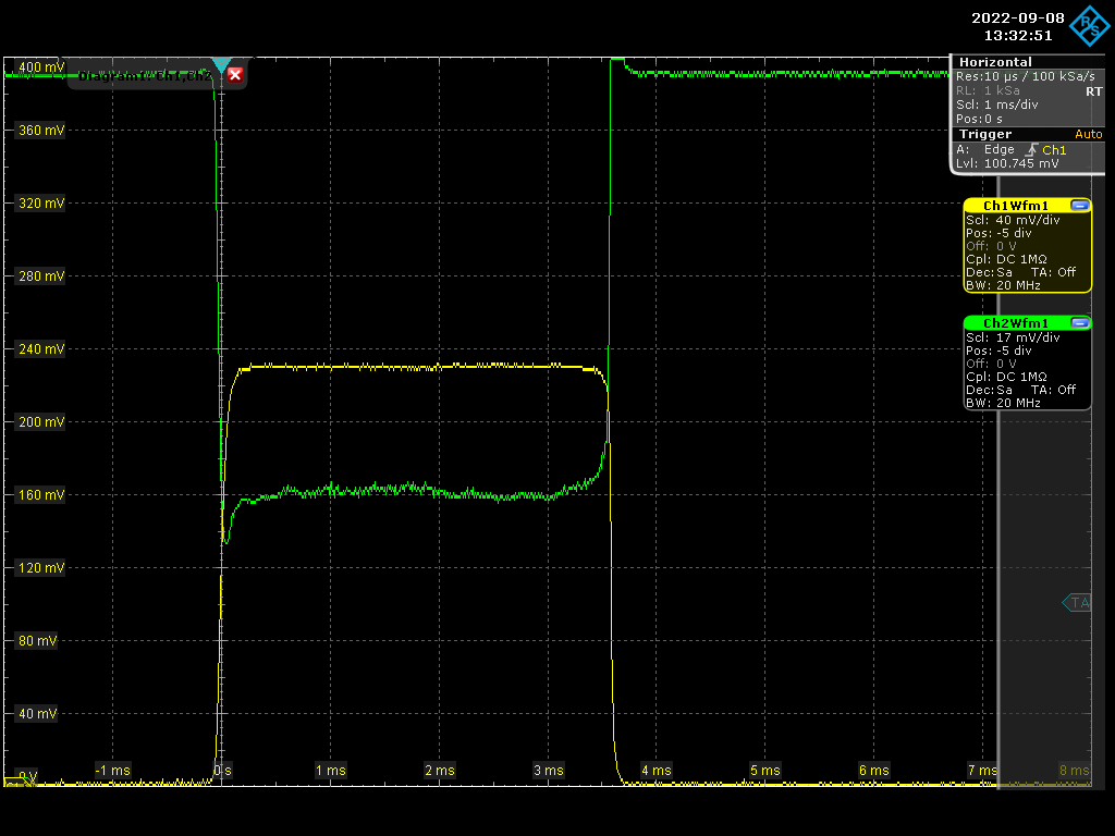
here is an image of the first attempts to lock... but the locking is quite difficult.
yellow : transmission
green : reflection
amplifier is still with 2nd stage only (Pout=~1W)
we are adding an AOM in the loop...
| Manar Amer wrote: |
|
Today, we played on the CEP but using the I-tune input of the Menhir Laser (+/- 5V maximal range).
unfortunately, one only saw a very weak improvement of the transmission by 10-20%... and the coupling improvement is almost zero.
the best improvement was for the maximal I-tune range (+5V) which maybe means that we could improve more the effect if were able to get a full range of 2pi for the CEP (instead of the present pi/2 range).
| Manar Amer wrote: |
|
Today we managed to observe the fundamental mode and stabilize the scan on it until we improved the alignment enough.
We see some coupling, but it is very week < 5% , We improved the alignment and the polarization, but there is still no explanation to why it is very low.
The mode shape is circular with radius = 0.89 mm at transmission point, ~ 40 cm from circular mirror.
One EOM was installed along the injection into the amplifier, we saw a drop in the power measured by the first stage monitor from ~ 8.2 mW to 7.2 mW
we improved the injection up to 7.6 mW, but it still fluctuates a lot. We need to be careful about it.
The error signal looks clean, but it is very week which is due to the weak coupling.
|
|
|
| Attachment 1: Screenshot_2022-09-08_0_133245.png
|  |
|
149
|
Thu Sep 8 14:58:51 2022 |
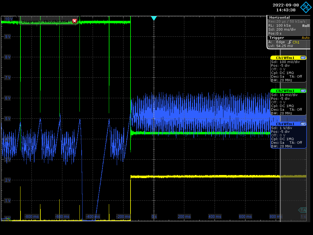
Manar Amer | Fixed | report | lasers and optics | Optical room | Locking Amplifier with Cavity | We managed to lock the cavity by adding the AOM , but the lock is still difficult to stabilize.
There is some high frequency compensated by the AOM at ~ 170 kHz (yet to understand from where it comes from)
| Manar Amer wrote: |
|
We played on the CEP using the USB command "id0=xxxxx" of the Menhir.
we put id0=48650 and we improved A LOT the transmission and coupling (~ 60%)
here is an image of the first attempts to lock... but the locking is quite difficult.
yellow : transmission
green : reflection
amplifier is still with 2nd stage only (Pout=~1W)
we are adding an AOM in the loop...
| Manar Amer wrote: |
|
Today, we played on the CEP but using the I-tune input of the Menhir Laser (+/- 5V maximal range).
unfortunately, one only saw a very weak improvement of the transmission by 10-20%... and the coupling improvement is almost zero.
the best improvement was for the maximal I-tune range (+5V) which maybe means that we could improve more the effect if were able to get a full range of 2pi for the CEP (instead of the present pi/2 range).
| Manar Amer wrote: |
|
Today we managed to observe the fundamental mode and stabilize the scan on it until we improved the alignment enough.
We see some coupling, but it is very week < 5% , We improved the alignment and the polarization, but there is still no explanation to why it is very low.
The mode shape is circular with radius = 0.89 mm at transmission point, ~ 40 cm from circular mirror.
One EOM was installed along the injection into the amplifier, we saw a drop in the power measured by the first stage monitor from ~ 8.2 mW to 7.2 mW
we improved the injection up to 7.6 mW, but it still fluctuates a lot. We need to be careful about it.
The error signal looks clean, but it is very week which is due to the weak coupling.
|
|
|
|
| Attachment 1: Screenshot_2022-09-08_2_144338.png
|  |
|
150
|
Thu Sep 8 18:28:51 2022 |
Manar Amer | Fixed | report | lasers and optics | Optical room | Locking Amplifier with Cavity | We wanted to increase the power of the amplifier to measure the transmission output at M2,
but locking the cavity again was very, very difficult.
We will try again tomorrow.
| Manar Amer wrote: |
|
We managed to lock the cavity by adding the AOM , but the lock is still difficult to stabilize.
There is some high frequency compensated by the AOM at ~ 170 kHz (yet to understand from where it comes from)
| Manar Amer wrote: |
|
We played on the CEP using the USB command "id0=xxxxx" of the Menhir.
we put id0=48650 and we improved A LOT the transmission and coupling (~ 60%)
here is an image of the first attempts to lock... but the locking is quite difficult.
yellow : transmission
green : reflection
amplifier is still with 2nd stage only (Pout=~1W)
we are adding an AOM in the loop...
| Manar Amer wrote: |
|
Today, we played on the CEP but using the I-tune input of the Menhir Laser (+/- 5V maximal range).
unfortunately, one only saw a very weak improvement of the transmission by 10-20%... and the coupling improvement is almost zero.
the best improvement was for the maximal I-tune range (+5V) which maybe means that we could improve more the effect if were able to get a full range of 2pi for the CEP (instead of the present pi/2 range).
| Manar Amer wrote: |
|
Today we managed to observe the fundamental mode and stabilize the scan on it until we improved the alignment enough.
We see some coupling, but it is very week < 5% , We improved the alignment and the polarization, but there is still no explanation to why it is very low.
The mode shape is circular with radius = 0.89 mm at transmission point, ~ 40 cm from circular mirror.
One EOM was installed along the injection into the amplifier, we saw a drop in the power measured by the first stage monitor from ~ 8.2 mW to 7.2 mW
we improved the injection up to 7.6 mW, but it still fluctuates a lot. We need to be careful about it.
The error signal looks clean, but it is very week which is due to the weak coupling.
|
|
|
|
|
|
151
|
Fri Sep 9 11:50:17 2022 |
Manar Amer | Fixed | report | lasers and optics | Optical room | Locking Amplifier with Cavity | We locked the cavity, and it is stable using the Transmission,
the high frequency that we thought could have a reason for instability, is due to the high power on the photo diode of the PDH box which can cause non-linearity effects in the signal.
We also closed the fan of the third stage and there was no significant change on the error signal and the piezo+AOM compensation signal.
| Manar Amer wrote: |
|
We managed to lock the cavity by adding the AOM , but the lock is still difficult to stabilize.
There is some high frequency compensated by the AOM at ~ 170 kHz (yet to understand from where it comes from)
| Manar Amer wrote: |
|
We played on the CEP using the USB command "id0=xxxxx" of the Menhir.
we put id0=48650 and we improved A LOT the transmission and coupling (~ 60%)
here is an image of the first attempts to lock... but the locking is quite difficult.
yellow : transmission
green : reflection
amplifier is still with 2nd stage only (Pout=~1W)
we are adding an AOM in the loop...
| Manar Amer wrote: |
|
Today, we played on the CEP but using the I-tune input of the Menhir Laser (+/- 5V maximal range).
unfortunately, one only saw a very weak improvement of the transmission by 10-20%... and the coupling improvement is almost zero.
the best improvement was for the maximal I-tune range (+5V) which maybe means that we could improve more the effect if were able to get a full range of 2pi for the CEP (instead of the present pi/2 range).
| Manar Amer wrote: |
|
Today we managed to observe the fundamental mode and stabilize the scan on it until we improved the alignment enough.
We see some coupling, but it is very week < 5% , We improved the alignment and the polarization, but there is still no explanation to why it is very low.
The mode shape is circular with radius = 0.89 mm at transmission point, ~ 40 cm from circular mirror.
One EOM was installed along the injection into the amplifier, we saw a drop in the power measured by the first stage monitor from ~ 8.2 mW to 7.2 mW
we improved the injection up to 7.6 mW, but it still fluctuates a lot. We need to be careful about it.
The error signal looks clean, but it is very week which is due to the weak coupling.
|
|
|
|
|
|
152
|
Fri Sep 9 12:45:19 2022 |
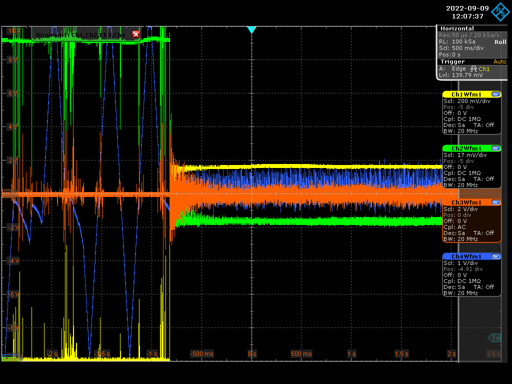
Manar Amer | Fixed | report | lasers and optics | Optical room | Locking Amplifier with Cavity | image of the lock with Coupling of ~ 60%
| Manar Amer wrote: |
|
We locked the cavity, and it is stable using the Transmission,
the high frequency that we thought could have a reason for instability, is due to the high power on the photo diode of the PDH box which can cause non-linearity effects in the signal.
We also closed the fan of the third stage and there was no significant change on the error signal and the piezo+AOM compensation signal.
| Manar Amer wrote: |
|
We managed to lock the cavity by adding the AOM , but the lock is still difficult to stabilize.
There is some high frequency compensated by the AOM at ~ 170 kHz (yet to understand from where it comes from)
| Manar Amer wrote: |
|
We played on the CEP using the USB command "id0=xxxxx" of the Menhir.
we put id0=48650 and we improved A LOT the transmission and coupling (~ 60%)
here is an image of the first attempts to lock... but the locking is quite difficult.
yellow : transmission
green : reflection
amplifier is still with 2nd stage only (Pout=~1W)
we are adding an AOM in the loop...
| Manar Amer wrote: |
|
Today, we played on the CEP but using the I-tune input of the Menhir Laser (+/- 5V maximal range).
unfortunately, one only saw a very weak improvement of the transmission by 10-20%... and the coupling improvement is almost zero.
the best improvement was for the maximal I-tune range (+5V) which maybe means that we could improve more the effect if were able to get a full range of 2pi for the CEP (instead of the present pi/2 range).
| Manar Amer wrote: |
|
Today we managed to observe the fundamental mode and stabilize the scan on it until we improved the alignment enough.
We see some coupling, but it is very week < 5% , We improved the alignment and the polarization, but there is still no explanation to why it is very low.
The mode shape is circular with radius = 0.89 mm at transmission point, ~ 40 cm from circular mirror.
One EOM was installed along the injection into the amplifier, we saw a drop in the power measured by the first stage monitor from ~ 8.2 mW to 7.2 mW
we improved the injection up to 7.6 mW, but it still fluctuates a lot. We need to be careful about it.
The error signal looks clean, but it is very week which is due to the weak coupling.
|
|
|
|
|
|
| Attachment 1: Screenshot_2022-09-09_0_120737.png
|  |
|
153
|
Fri Sep 9 12:49:44 2022 |
Manar Amer | Fixed | report | lasers and optics | Optical room | Locking Amplifier with Cavity | Alignment was improved to ~ 1.2 V on the photodiode.
Only the second stage was on with ~ 1 W output from amplifier
we measured the transmission from S2 to be 2.3 mW
| Manar Amer wrote: |
|
image of the lock with Coupling of ~ 60%
| Manar Amer wrote: |
|
We locked the cavity, and it is stable using the Transmission,
the high frequency that we thought could have a reason for instability, is due to the high power on the photo diode of the PDH box which can cause non-linearity effects in the signal.
We also closed the fan of the third stage and there was no significant change on the error signal and the piezo+AOM compensation signal.
| Manar Amer wrote: |
|
We managed to lock the cavity by adding the AOM , but the lock is still difficult to stabilize.
There is some high frequency compensated by the AOM at ~ 170 kHz (yet to understand from where it comes from)
| Manar Amer wrote: |
|
We played on the CEP using the USB command "id0=xxxxx" of the Menhir.
we put id0=48650 and we improved A LOT the transmission and coupling (~ 60%)
here is an image of the first attempts to lock... but the locking is quite difficult.
yellow : transmission
green : reflection
amplifier is still with 2nd stage only (Pout=~1W)
we are adding an AOM in the loop...
| Manar Amer wrote: |
|
Today, we played on the CEP but using the I-tune input of the Menhir Laser (+/- 5V maximal range).
unfortunately, one only saw a very weak improvement of the transmission by 10-20%... and the coupling improvement is almost zero.
the best improvement was for the maximal I-tune range (+5V) which maybe means that we could improve more the effect if were able to get a full range of 2pi for the CEP (instead of the present pi/2 range).
| Manar Amer wrote: |
|
Today we managed to observe the fundamental mode and stabilize the scan on it until we improved the alignment enough.
We see some coupling, but it is very week < 5% , We improved the alignment and the polarization, but there is still no explanation to why it is very low.
The mode shape is circular with radius = 0.89 mm at transmission point, ~ 40 cm from circular mirror.
One EOM was installed along the injection into the amplifier, we saw a drop in the power measured by the first stage monitor from ~ 8.2 mW to 7.2 mW
we improved the injection up to 7.6 mW, but it still fluctuates a lot. We need to be careful about it.
The error signal looks clean, but it is very week which is due to the weak coupling.
|
|
|
|
|
|
|
|
173
|
Fri Jan 6 12:33:18 2023 |
Ronic Chiche | Fixed | info | lasers and optics | Optical room | Laser Menhir reinstallation + CVBG + fiber injection | The lab purchased the Menhir laser @ 216MHz.
it has been sent back to Menhir photonics for inspection, and then is now at lab.
it has been reinstalled to the SBOX setup with injection in a CVBG for pulse stretching before amplification.
the power after CVBG is 24mV.
the power coupled to the fiber is only 6.4mW => to be optimized.
the spectrum has been mesured after CVBG and seems correct : picture is attached.
|
| Attachment 1: MenhirJan2022.PNG
|  |
|
211
|
Thu Apr 4 21:48:16 2024 |
Xinyi Lu | Fixed | info | lasers and optics | Optical room | Larger beam size & Spectrum | - We re-measured the gain before moving the mirror. Gain ~9000 was achieved at 3A, but as the power increased, the gain dropped and was difficult to optimize. In fact, we found that each day the gain was a little higher than the previous day.
| Amp current (A) |
Injection power (W) |
Circulating power (kW) |
Gain(coupling~0.7) |
Finesse |
| 3 |
23.5 |
213 |
9046 |
33595 |
| 4 |
35.5 |
309 |
8692 |
32933 |
| 5 |
47 |
390 |
8292 |
32165 |
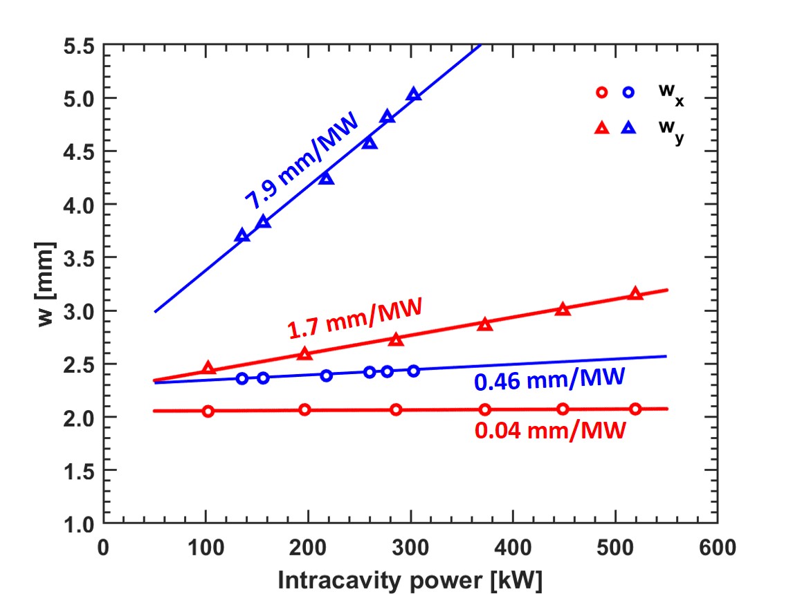
- We then moved the M3 spherical mirror 1.7mm to make the beam size larger and measured the variation in cavity mode size at different powers. (Figure 1, red is the original result and blue is the result for a larger cavity mode). It is clear that the larger the cavity mode, the larger the slope. The new slope of w_y is 7.9mm/MW. Tomorrow we will make the cavity mode smaller (like in Carstens' paper) and compare the three curves.
- It is not simple to compare the gain variations of different cavity modes because it takes more time to optimize the telescope and alignment. Ronic suggested that we could compensate for the cavity mode variation by moving the spherical mirror to see how the gain changes at different powers while keeping the cavity mode unchanged.
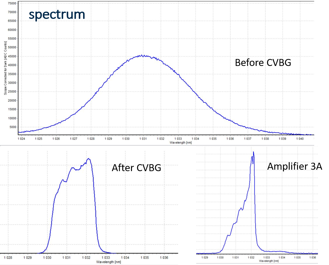
- In addition, we measured the spectrum of the menhir laser, after cvgb, amplifier output at 3A (Figure 2). We found that the peak changed from 1031 nm to 1032 nm after CVBG, probably because of the imperfect alignment of CVBG.
| Xinyi Lu wrote: |
|
- Today we moved the position of the D-shaped mirror at 6A. When motor1 (vertical) is 0.2mm away from the spot, the power in the cavity rises from 457kW to 483kW. Gain=8407 is similar to that at low power (Gain=8511). So the D-shaped mirror lost some of the gain in the previous experiments. At 4A and 5A we did not move the D-shaped mirror. (Figure 1)
- At 8A, we got 553 kW inside the cavity for one minute (Figure 2). The pump temperature is higher than yesterday (up to 34°C).
- At 7.5A and 8A, the cavity can remain stably locked, but the power fluctuation in the cavity is so large that it is difficult to optimize the alignment. This may be due to the short time the amplifier was on, the pump temperature, amplifier pointing and power fluctuations, and thermal effects in the cavity....... The amplifier operated differently at different moments.
- We measured the spectrum of the amplified laser. (Figure 3) The peak is 1032.2 nm. We will optimize the alignment and increase the power to optimize this measurement.
- Next arrangement
Thursday: larger laser beam size
Friday: smaller laser beam size
Monday: finesse measurement with CW laser (Firstly check the possibility of measuring with pulsed laser)
| Xinyi Lu wrote: |
|
Yesterday, Ronic, Xing, Qili and I achieved a more stable 520kW power at 7.5A (71W injection) by optimizing the alignment and locking parameters. (Figure 1)
- The cavity can be stable locked when airflow is on. At 7.5A, the pump temperature is about 28℃. The chiller temperature didn't change, to the same 23 ℃ setting. We can try 8A later (75W injection) for a short time;
- Figure 2 demonstrates the cavity mode variation, wy/Pc ~ 1.7 mm/MW, half that of the OL paper (3.3 mm/MW). The thermal deformation of our device is much smaller.
- The experimental data are shown in Figure 3. Figure 4 shows the injection power vs circulating power.
- There are some tests that can be done at the moment. I'll update on the elog after discussing the necessity today. ^_^
|
|
|
| Attachment 1: cavitymode_vs_power_bigger.jpg
|  |
| Attachment 2: spectrum.png
|  |
|
126
|
Thu Aug 11 19:27:09 2022 |
Ronic Chiche | Fixed | info | lasers and optics | detectors and electronics | Optical room | Koheras CW laser lock on FP cavity | I locked the Koheras CW on the FP cavity but the lock was pretty noisy and very difficult to acquire.
I tried to produce some modulation sidebands close to 216MHz to measure the Finesse but the power loss was very small so, the signal to extract the Finesse would be unreadable !
(generator voltage was at maximum Vout = 0.5Vrms on 50 ohms... is it normal ? or the used 10GHz EOM suffers some problems ?)
At one moment, I lost the lock and was not able to find it again... it seems the Koheras is too noisy for this cavity (may be is it a good news for the Finesse ?).
Tomorrow, I will try to use the OEwave + amplifier to lock the cavity.
|
|
76
|
Wed Apr 20 19:05:37 2022 |
Manar Amer | Fixed | report | lasers and optics | Optical room | KBox Alignment | Starting with the alignment of the KBox using CW Koheras.
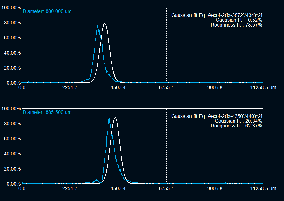
The size of the CW output from the collimator at 1 meter from is ~ 2.4 mm, to be adjusted with lenses to match the cavity !!! (attached image)
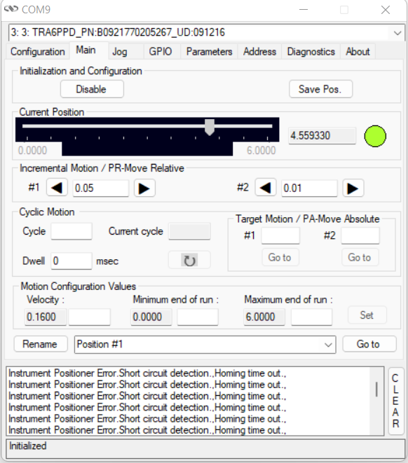
For the 2 alignment mirrors, I am only able to control 3 axes for now (motor issue for the fourth to be fixed !!) , Horizontal and vertical for Ma1 and Horizontal for Ma2(closes to injection window).
Started with only irises placed on both the M1 and M2. Placed a beam profiler at the window behind M2 to observe an output beam.
Motors position for the 3 axes and beam shape and position after M2 attached. |
| Attachment 1: CW_Koheras_1meter_ColimatorOutput_NE40A_NE10B_NE01A_Beam.bmp
|
| Attachment 2: CW_Koheras_1meter_ColimatorOutput_NE40A_NE10B_NE01A_BeamFit.png
|  |
| Attachment 3: Ma1_Horizontal_Position.png
|  |
| Attachment 4: Ma1_Vertical_Position.png
|  |
| Attachment 5: Ma2_Horizontal_Position.png
|  |
| Attachment 6: Transmission_M2_Irises_No_Mirrors_Beam.jpg
|  |
| Attachment 7: Transmission_M2_Irises_No_Mirrors_BeamFit.png
|  |
|
241
|
Thu Sep 4 17:35:50 2025 |
Ronic Chiche | Fixed | info | lasers and optics | detectors and electronics | Optical room | Installation of the avalanche photodiode | After installing the 2nd EOM, we had some trouble to be able to lock again.
One possible reason was the very low signal level in transmission, which is important to trigger the locking system (and stop it).
See the Alice post for details, but we were able to measure only once the Finesse of the cavity at around 2600.
After the Finesse measurement, we opened the box to change the M1 mirror... so the box is at ambient pressure now.
I took back the avalanche photodiode from the Minicav room and installed it on the setup to replace the FPC transmission photodiode.
Now, the transmission peaks are at the 1V level, and it's very easy to trigger on...
The system locked very easily, even without being under vacuum.
It will help if we need to inject very low power laser (e.g. OEwaves after 2x EOM and AOM).
|
|
114
|
Tue Jul 12 18:53:55 2022 |
Manar Amer | Fixed | report | lasers and optics | detectors and electronics | Optical room | Installation of D-shaped mirror / Alignment | To prepare for the amplifier. I installed the D-shapped mirrors after cleaning (using aceton and ethanol) between the cavity 2 mirrors.
Before closing, I observed the back reflection from M1 (injection mirror). both the injection and reflection lines were off, due to that there was an internal reflection hitting the walls of the cavity.
I tried to correct it by slightly adjusting on M1 without losing the mode, but unfortunately we lost it.
Tried to go back to the original position using the reflection iris reference, with no success.
Cavity axis is lost, and we need to align again.
| Manar Amer wrote: |
|
a Finesse of 30k with the present mirrors :
T1=120 ppm ;A1=(2.6+1) ppm;
T2=1.5 ppm ;A2=(4.5+0.27) ppm;
corresponds to 39 ppm of additional losses for each mirror and a theoretical gain of about 11k.
| Manar Amer wrote: |
|
Yesterday evening the cavity was Vacuum pumped up to pressure of 5.5*10^-2 and locked
changed FSR to be 216.662 MHz and alignment a little and measured the Finesse
in Vacuum we have average Finesse = 30341.6265
FWHM (KHz) = 7.0592
Finesse = 30692.1961
FWHM (KHz) = 7.2186
Finesse = 30014.556
FWHM (KHz) = 7.1051
Finesse = 30493.7635
FWHM (KHz) = 7.1079
Finesse = 30481.9812
FWHM (KHz) = 7.1413
Finesse = 30339.2695
FWHM (KHz) = 7.1624
Finesse = 30249.776
FWHM (KHz) = 7.0239
Finesse = 30846.2719
FWHM (KHz) = 7.2614
Finesse = 29837.6477
FWHM (KHz) = 7.1935
Finesse = 30119.1768
| Manar Amer wrote: |
|
The FSR of the 2 mirror (plan-spherical) Cavity was adjusted from 210 MHz to reach 216.643 MHz
it was done by having two reference irises, one at the injection point and one at the reflection
then changing the position of injection plan mirror to slightly closer distance and monitoring the reflection on the oscilloscope to be max.
The cavity modes were still seen, and we had to only improve the injection alignment after.
Me and Ronic locked in air and measured the Finesse, which was bigger by ~ 20%
average Finesse = 30208.53614
FWHM (KHz) = 7.0179
Finesse = 30869.9522
FWHM (KHz) = 7.1257
Finesse = 30403.005
FWHM (KHz) = 7.1287
Finesse = 30390.4014
FWHM (KHz) = 7.2884
Finesse = 29724.5531
FWHM (KHz) = 7.3055
Finesse = 29654.769
| Manar Amer wrote: |
|
Update for Finesse measurement, The cavity was put under vacuum ~ 1.1*10^-1 mbar
and the alignment and coupling improved.
FSR = 210.1 MHz
Average Finesse = 25686.46222
FWHM (KHz) = 8.2387
Finesse = 25501.5659
FWHM (KHz) = 8.2028
Finesse = 25613.2858
FWHM (KHz) = 8.0978
Finesse = 25945.3289
FWHM (KHz) = 8.1744
Finesse = 25702.3142
FWHM (KHz) = 8.1847
Finesse = 25669.8163
Concluded from Ronic's calculations, this could be the maximum finesse we might be able to obtain with this setup
with Gain ~ 8000
On Monday we adjust the frequency to match 2160.66 MHz and lock the Pulsed,
at the same time start we start with the CELIA amplifier.
| Manar Amer wrote: |
|
The cavity was realigned using irises instead of pinholes, gave a better alignment.
The inside of the box, the spherical and the injection mirror were cleaned and placed back inside the box.
we see beating of fundamental mode, previously at the transmission point we placed a wedge to split the beam which resulted in an elliptical mode
we removed it and placed a very thin beam splitter, the beam is circular now.
The cavity was locked in air at a coupling of ~ 60-70 %
Finesse and line width measured five readings with a Finesse average 25095.08884 of a Gain ~ 8000
FWHM (KHz) = 8.2928
Finesse = 25323.0544
FWHM (KHz) = 7.9202
Finesse = 26514.4395
FWHM (KHz) = 8.5834
Finesse = 24465.8636
FWHM (KHz) = 8.4571
Finesse = 24831.2419
FWHM (KHz) = 8.6275
Finesse = 24340.8448
Theoretical and expected Finesse for the 2 mirror setup with the losses is calculated by Ronic for comparison between four and 2 mirror setup.
| Manar Amer wrote: |
|
The SBox cavity setup was changed to have only 2 mirrors M1 plane and M2 spherical, both from ThomX
Distance between the mirror ~ 72 cm , increased from 70 cm to take into account the thickness of the ThomX mirrors
Two lenses (300 mm @ 50 cm , 200 @ 104 cm) were placed to have the beam radius ~ 0.55 mm.
The cavity was locked with a coupling of 60 %, for Finesse measurement the sweep was taken over 100 KHz of 2 seconds.
FSR ~ 210.00 MHz, line width ~ 8.56 KHz, Finesse ~ 24 500 .
|
|
|
|
|
|
|
|
117
|
Fri Jul 22 17:10:06 2022 |
Manar Amer | Fixed | report | lasers and optics | detectors and electronics | Optical room | Installation of D-shaped mirror / Alignment | The D-shaped mirrors are installed properly and not cutting the path of the beam.
The cavity has been aligned again and 00 modes beating observed, and external reference points has been placed.
| Manar Amer wrote: |
|
To prepare for the amplifier. I installed the D-shapped mirrors after cleaning (using aceton and ethanol) between the cavity 2 mirrors.
Before closing, I observed the back reflection from M1 (injection mirror). both the injection and reflection lines were off, due to that there was an internal reflection hitting the walls of the cavity.
I tried to correct it by slightly adjusting on M1 without losing the mode, but unfortunately we lost it.
Tried to go back to the original position using the reflection iris reference, with no success.
Cavity axis is lost, and we need to align again.
| Manar Amer wrote: |
|
a Finesse of 30k with the present mirrors :
T1=120 ppm ;A1=(2.6+1) ppm;
T2=1.5 ppm ;A2=(4.5+0.27) ppm;
corresponds to 39 ppm of additional losses for each mirror and a theoretical gain of about 11k.
| Manar Amer wrote: |
|
Yesterday evening the cavity was Vacuum pumped up to pressure of 5.5*10^-2 and locked
changed FSR to be 216.662 MHz and alignment a little and measured the Finesse
in Vacuum we have average Finesse = 30341.6265
FWHM (KHz) = 7.0592
Finesse = 30692.1961
FWHM (KHz) = 7.2186
Finesse = 30014.556
FWHM (KHz) = 7.1051
Finesse = 30493.7635
FWHM (KHz) = 7.1079
Finesse = 30481.9812
FWHM (KHz) = 7.1413
Finesse = 30339.2695
FWHM (KHz) = 7.1624
Finesse = 30249.776
FWHM (KHz) = 7.0239
Finesse = 30846.2719
FWHM (KHz) = 7.2614
Finesse = 29837.6477
FWHM (KHz) = 7.1935
Finesse = 30119.1768
| Manar Amer wrote: |
|
The FSR of the 2 mirror (plan-spherical) Cavity was adjusted from 210 MHz to reach 216.643 MHz
it was done by having two reference irises, one at the injection point and one at the reflection
then changing the position of injection plan mirror to slightly closer distance and monitoring the reflection on the oscilloscope to be max.
The cavity modes were still seen, and we had to only improve the injection alignment after.
Me and Ronic locked in air and measured the Finesse, which was bigger by ~ 20%
average Finesse = 30208.53614
FWHM (KHz) = 7.0179
Finesse = 30869.9522
FWHM (KHz) = 7.1257
Finesse = 30403.005
FWHM (KHz) = 7.1287
Finesse = 30390.4014
FWHM (KHz) = 7.2884
Finesse = 29724.5531
FWHM (KHz) = 7.3055
Finesse = 29654.769
| Manar Amer wrote: |
|
Update for Finesse measurement, The cavity was put under vacuum ~ 1.1*10^-1 mbar
and the alignment and coupling improved.
FSR = 210.1 MHz
Average Finesse = 25686.46222
FWHM (KHz) = 8.2387
Finesse = 25501.5659
FWHM (KHz) = 8.2028
Finesse = 25613.2858
FWHM (KHz) = 8.0978
Finesse = 25945.3289
FWHM (KHz) = 8.1744
Finesse = 25702.3142
FWHM (KHz) = 8.1847
Finesse = 25669.8163
Concluded from Ronic's calculations, this could be the maximum finesse we might be able to obtain with this setup
with Gain ~ 8000
On Monday we adjust the frequency to match 2160.66 MHz and lock the Pulsed,
at the same time start we start with the CELIA amplifier.
| Manar Amer wrote: |
|
The cavity was realigned using irises instead of pinholes, gave a better alignment.
The inside of the box, the spherical and the injection mirror were cleaned and placed back inside the box.
we see beating of fundamental mode, previously at the transmission point we placed a wedge to split the beam which resulted in an elliptical mode
we removed it and placed a very thin beam splitter, the beam is circular now.
The cavity was locked in air at a coupling of ~ 60-70 %
Finesse and line width measured five readings with a Finesse average 25095.08884 of a Gain ~ 8000
FWHM (KHz) = 8.2928
Finesse = 25323.0544
FWHM (KHz) = 7.9202
Finesse = 26514.4395
FWHM (KHz) = 8.5834
Finesse = 24465.8636
FWHM (KHz) = 8.4571
Finesse = 24831.2419
FWHM (KHz) = 8.6275
Finesse = 24340.8448
Theoretical and expected Finesse for the 2 mirror setup with the losses is calculated by Ronic for comparison between four and 2 mirror setup.
| Manar Amer wrote: |
|
The SBox cavity setup was changed to have only 2 mirrors M1 plane and M2 spherical, both from ThomX
Distance between the mirror ~ 72 cm , increased from 70 cm to take into account the thickness of the ThomX mirrors
Two lenses (300 mm @ 50 cm , 200 @ 104 cm) were placed to have the beam radius ~ 0.55 mm.
The cavity was locked with a coupling of 60 %, for Finesse measurement the sweep was taken over 100 KHz of 2 seconds.
FSR ~ 210.00 MHz, line width ~ 8.56 KHz, Finesse ~ 24 500 .
|
|
|
|
|
|
|
|
|
182
|
Wed Jan 17 21:11:59 2024 |
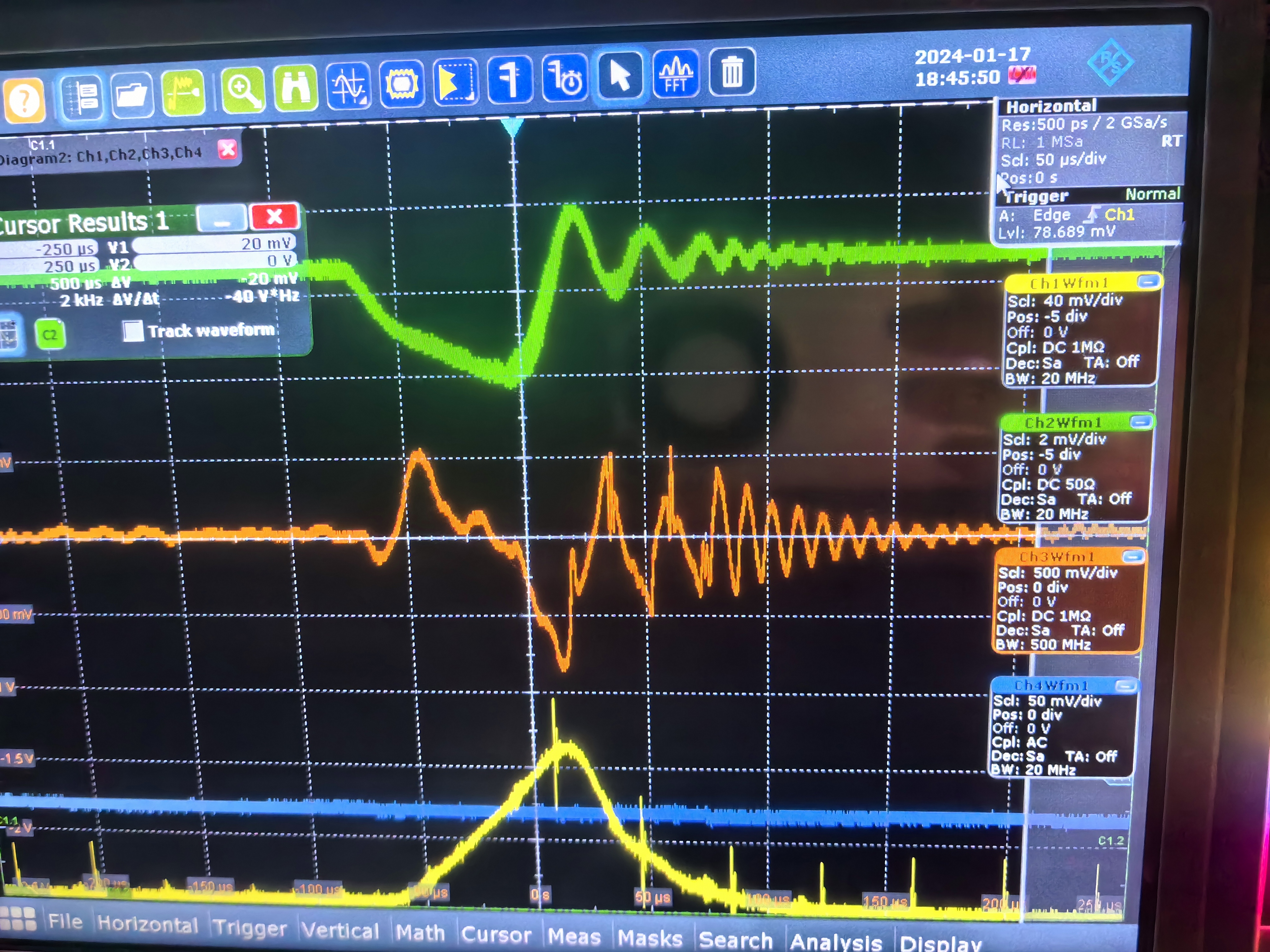
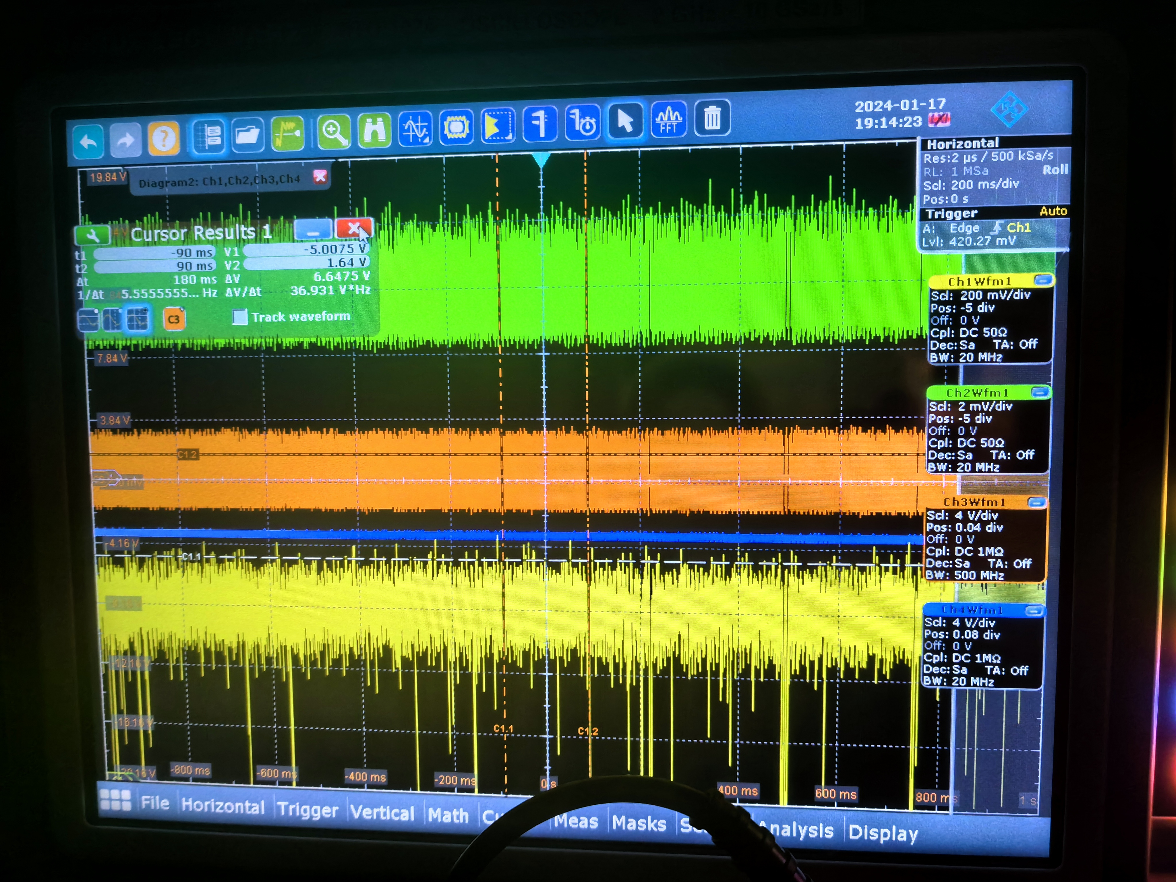
Xinyi Lu | Fixed | info | lasers and optics | Optical room | Install new mirrors | Today, Ronic and I installed the new mirrors and got resonance. We can see the oscillations in this high-finesse case. We haven't carefully optimized the alignment. Coupling efficiency is about 15% and the cavity can be locked.
Tomorrow we will optimize the alignment and locking, and measure the finesse. |
| Attachment 1: New_mirrors.png
|  |
| Attachment 2: oscillations.jpg
|  |
| Attachment 3: locking.jpg
|  |
|
183
|
Thu Jan 18 22:14:03 2024 |
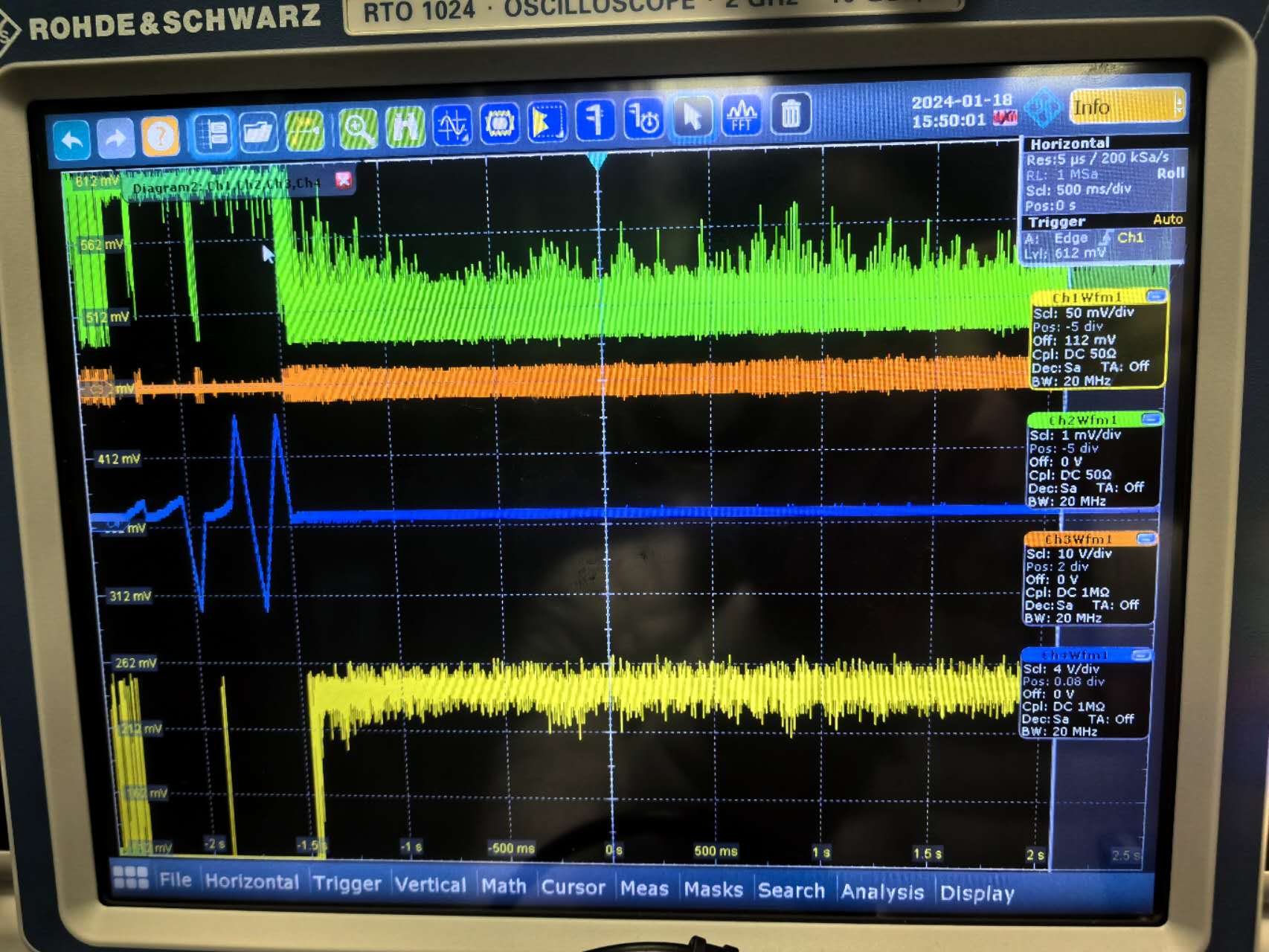
Xinyi Lu | Fixed | info | lasers and optics | Optical room | Install new mirrors | - In the last two days, Ronic and I installed new mirrors after cleaning the environment, and locked the cavity.
- We added an AOM to feedback on the high-frequency noise, but the locking condition was still not good enough. We found out that the signal generator available for this AOM has a long delay time (3 us), which may lead to low feedback bandwidth. So tomorrow we will use another AOM and signal generator to optimize the locking.
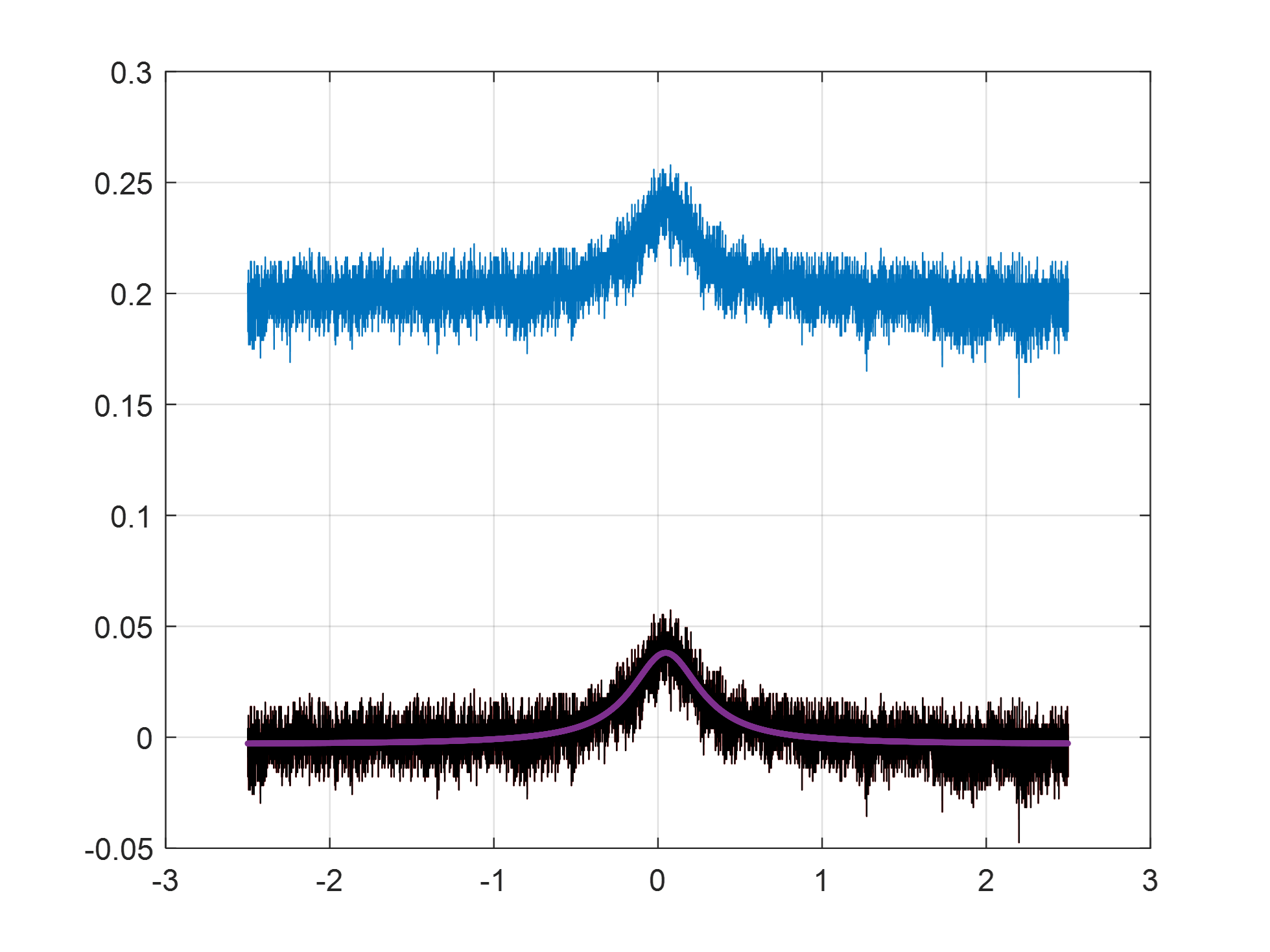
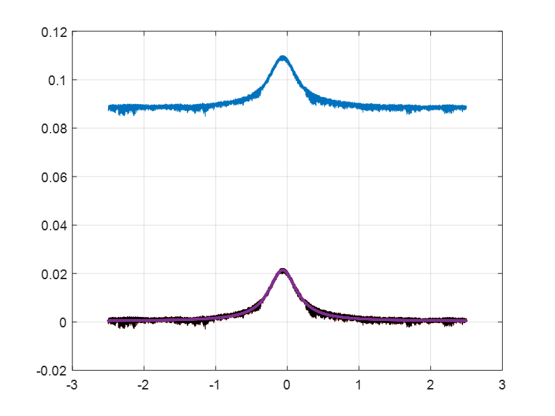
- Under this not good enough locking, we measured the finesse. Unfortunately, the finesse was measured as 15,478, which is much lower than the expected 42,000. It means that about 260ppm of additional loss was introduced. We will measure the finesse again after optimizing the locking and coupling.
By the way, attached are the delay time results for phase modulation of different signal generators:
- RIGOL DG4162: 0.7 us (best)
- SIGLENT SDG6022X: 3 us
- SIGLENT SDG7032A: 2.9 us |
| Attachment 1: New_mirrors.png
|  |
| Attachment 2: finesse.png
|  |
| Attachment 3: locking.jpg
|  |
|
184
|
Mon Jan 22 18:18:01 2024 |
Xinyi Lu | Fixed | info | lasers and optics | Optical room | Install new mirrors | - Today, Ronic and I changed the signal generator to a low-noise one (with a delay time of only 0.5 us). Then we moved the D-shaped mirrors, optimized the alignment and locking. We re-measured the finesse and it is 16,760. It improves but not much.
- Tomorrow, we will clean the environment, open the cavity, and use UV light to see if there is any dust on the surface of the mirrors.
| Xinyi Lu wrote: |
|
- In the last two days, Ronic and I installed new mirrors after cleaning the environment, and locked the cavity.
- We added an AOM to feedback on the high-frequency noise, but the locking condition was still not good enough. We found out that the signal generator available for this AOM has a long delay time (3 us), which may lead to low feedback bandwidth. So tomorrow we will use another AOM and signal generator to optimize the locking.
- Under this not good enough locking, we measured the finesse. Unfortunately, the finesse was measured as 15,478, which is much lower than the expected 42,000. It means that about 260ppm of additional loss was introduced. We will measure the finesse again after optimizing the locking and coupling.
By the way, attached are the delay time results for phase modulation of different signal generators:
- RIGOL DG4162: 0.7 us (best)
- SIGLENT SDG6022X: 3 us
- SIGLENT SDG7032A: 2.9 us
|
|
| Attachment 1: New_finesse.png
|  |
|
185
|
Wed Jan 24 20:33:27 2024 |
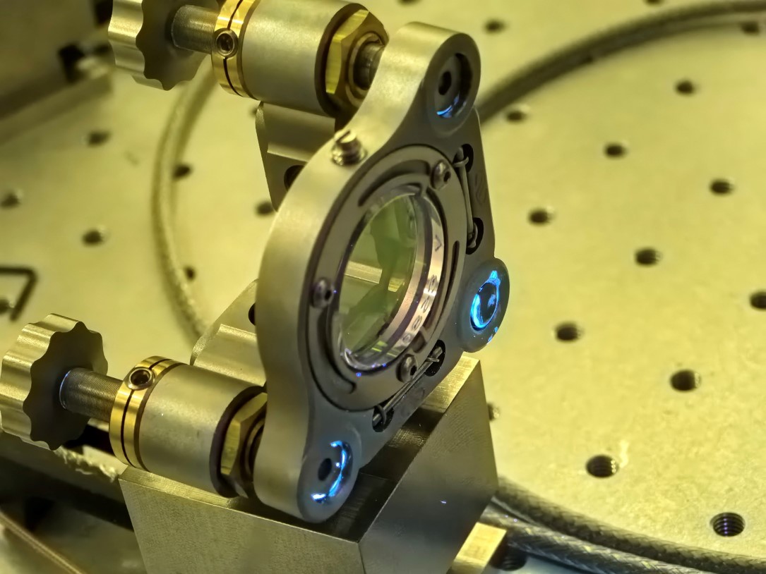
Xinyi Lu | Fixed | info | lasers and optics | Optical room | Install new mirrors | Yesterday we checked the mirrors with UV light and there was some dust on the mirrors, especially M2.
Today, Daniele, Ronic and I removed M2 and observed it with a microscope. It was indeed dirty, despite we were careful in installing it before. After that we cleaned it with alcohol and mirror paper, then with a spin coater and pure water. After cleaning, we observed it again and it was much better but not perfect. Then we installed the M2 back. But we haven't succeeded in alignment and getting resonance.
Tomorrow is the newcomer's day, so we will continue with the cleaning and measurements on Friday.
| Xinyi Lu wrote: |
|
- Today, Ronic and I changed the signal generator to a low-noise one (with a delay time of only 0.5 us). Then we moved the D-shaped mirrors, optimized the alignment and locking. We re-measured the finesse and it is 16,760. It improves but not much.
- Tomorrow, we will clean the environment, open the cavity, and use UV light to see if there is any dust on the surface of the mirrors.
| Xinyi Lu wrote: |
|
- In the last two days, Ronic and I installed new mirrors after cleaning the environment, and locked the cavity.
- We added an AOM to feedback on the high-frequency noise, but the locking condition was still not good enough. We found out that the signal generator available for this AOM has a long delay time (3 us), which may lead to low feedback bandwidth. So tomorrow we will use another AOM and signal generator to optimize the locking.
- Under this not good enough locking, we measured the finesse. Unfortunately, the finesse was measured as 15,478, which is much lower than the expected 42,000. It means that about 260ppm of additional loss was introduced. We will measure the finesse again after optimizing the locking and coupling.
By the way, attached are the delay time results for phase modulation of different signal generators:
- RIGOL DG4162: 0.7 us (best)
- SIGLENT SDG6022X: 3 us
- SIGLENT SDG7032A: 2.9 us
|
|
|
| Attachment 1: M2.jpg
|  |
|
215
|
Thu Apr 11 19:09:21 2024 |
Xinyi Lu | Fixed | info | lasers and optics | Optical room | Install 2-mirror cavity | Today, Viktor and I started installing the two-mirror cavity.
- Firstly, we cleaned the environment and the dust counter showed good cleanliness
- After opening the cavity we tried to determine the source of the strange spot with a laser detection card and found that the beam was very close to the front edge of the longitudinal D-shaped mirror. In addition there was nothing else strange.
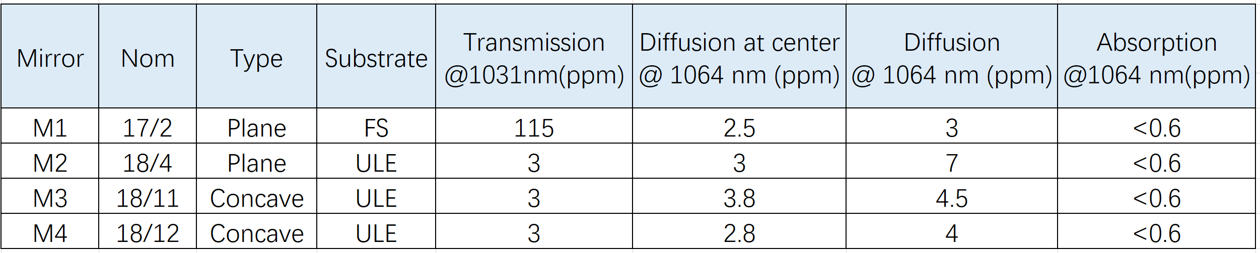
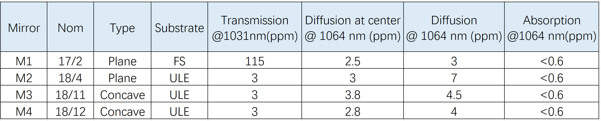
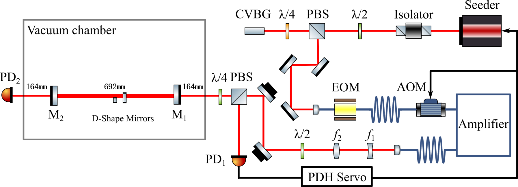
- The setup of the two-mirror cavity is shown in Figure 1. We have to use the menhir laser of 216MHz. The mirrors used are shown in Figure 2.
- We have installed the M2 and will continue the installation tomorrow. |
| Attachment 1: 2_mirror_setup.png
|  |
| Attachment 2: mirrors.png
|  |
|