| ID |
Date |
Author |
Status |
Type |
Category |
Location |
Title |
|
115
|
Tue Jul 12 19:07:50 2022 |
Manar Amer | Fixed | report | lasers and optics | detectors and electronics | software | Optical room | CELIA amplifier installation |
The amplifier was installed on the optical table next to SBox table.
The CVBG that will be used for stretching before amplification needs cleaning (they are very fragile, 'ask victor for best method')
The software to drive the diodes of the amplifier we have is not the compatible one. |
|
116
|
Fri Jul 22 17:07:32 2022 |
Manar Amer | Fixed | report | lasers and optics | detectors and electronics | software | Optical room | CELIA amplifier installation + chiller |
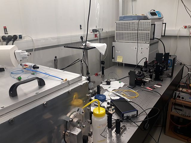
Amplifier placed next to the pulsed laser on the table under the airflow
The output is in free space with height from the table of about 10 cm, note the injection height into the cavity is between 14 - 15 cm.
a power cable is placed but not plugged.
Connection to the computer is made using USB B on amplifier to USB A (note need a longer cable, the available on is too short)
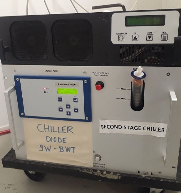
The cooling, to be connected to an outside chiller, will use the bottom one shown in the image attached.
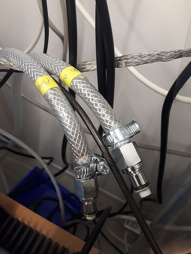
The two water tubes, from chiller to amplifier, has been marked. The size of the tubes from the amplifier fit inside the tubes from the chiller.
| Manar Amer wrote: |
|
The amplifier was installed on the optical table next to SBox table.
The CVBG that will be used for stretching before amplification needs cleaning (they are very fragile, 'ask victor for best method')
The software to drive the diodes of the amplifier we have is not the compatible one.
|
|
| Attachment 1: WhatsApp_Image_2022-07-22_at_4.26.24_PM.jpg
|
 |
| Attachment 2: WhatsApp_Image_2022-07-22_at_4.26.24_PM.jpg
|
 |
| Attachment 3: WhatsApp_Image_2022-07-22_at_5.02.24_PM.jpg
|
 |
|
118
|
Fri Jul 22 18:00:21 2022 |
Manar Amer | Fixed | report | lasers and optics | detectors and electronics | software | Optical room | Alignment / Table setup |
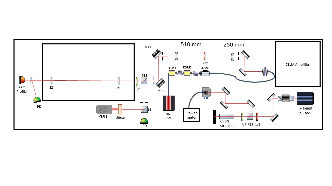
The current setup of the optical table attached.
The cavity is aligned and the lock of the fundamental mode has been attempted, but the mode is drifting too quickly to be able to follow.
I have placed the cavity under vacuum for a better stability.
a simple telescope for the CW was adjusted to having 2 lenses of 300 mm placed ~ 250 mm away from the colimator and 200 mm lens placed after it with 510 mm.
|
| Attachment 1: 20220722_table_setup.jpg
|
 |
| Attachment 2: 20220722_tablesetup.jpg
|
 |
|
119
|
Fri Jul 22 18:19:13 2022 |
Manar Amer | Fixed | report | lasers and optics | detectors and electronics | software | Optical room | CVBG stretching / Fiber Injection |
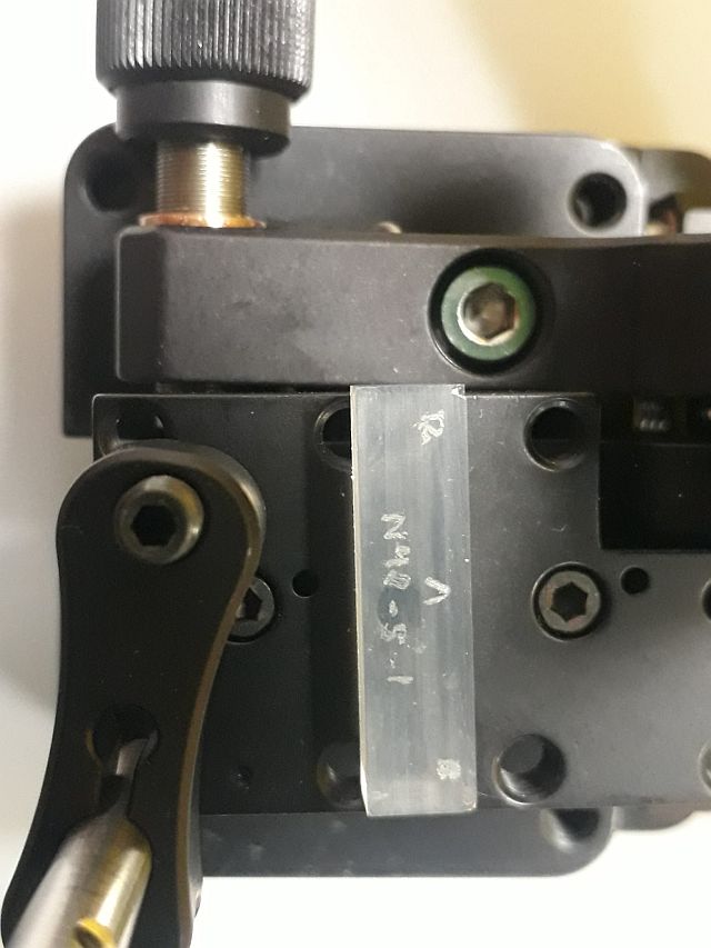
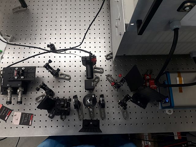
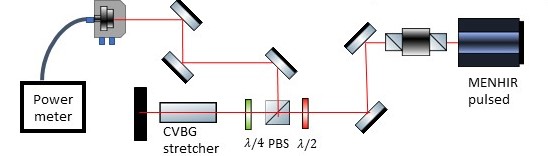
Before injecting into the amplifier, the pulse needs to be stretched using a CVBG, type attached.
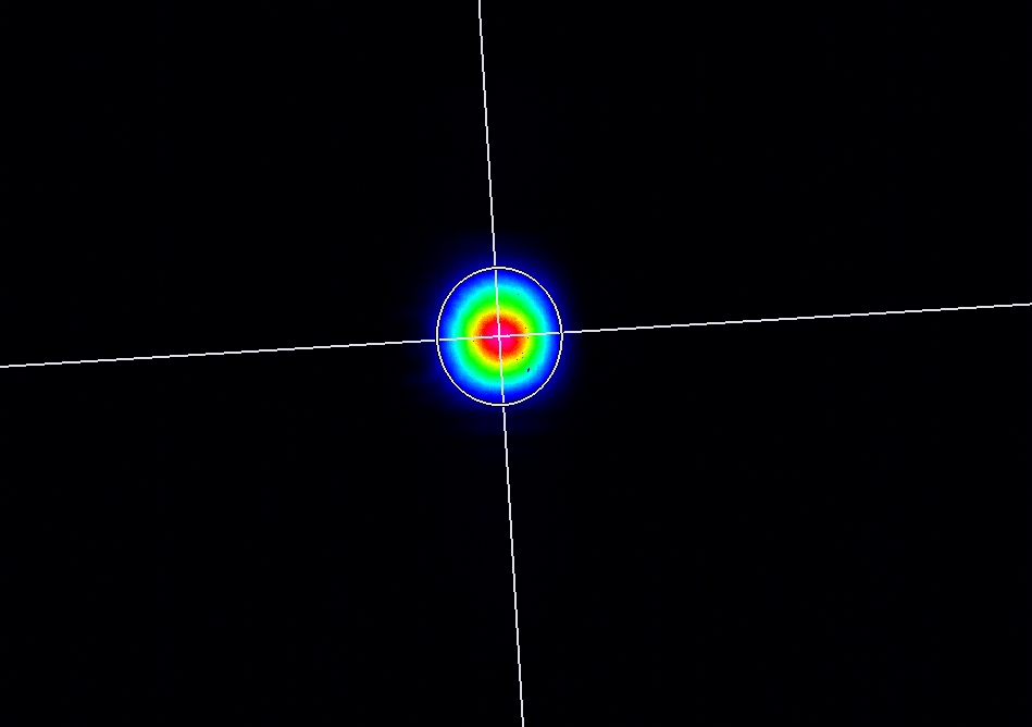
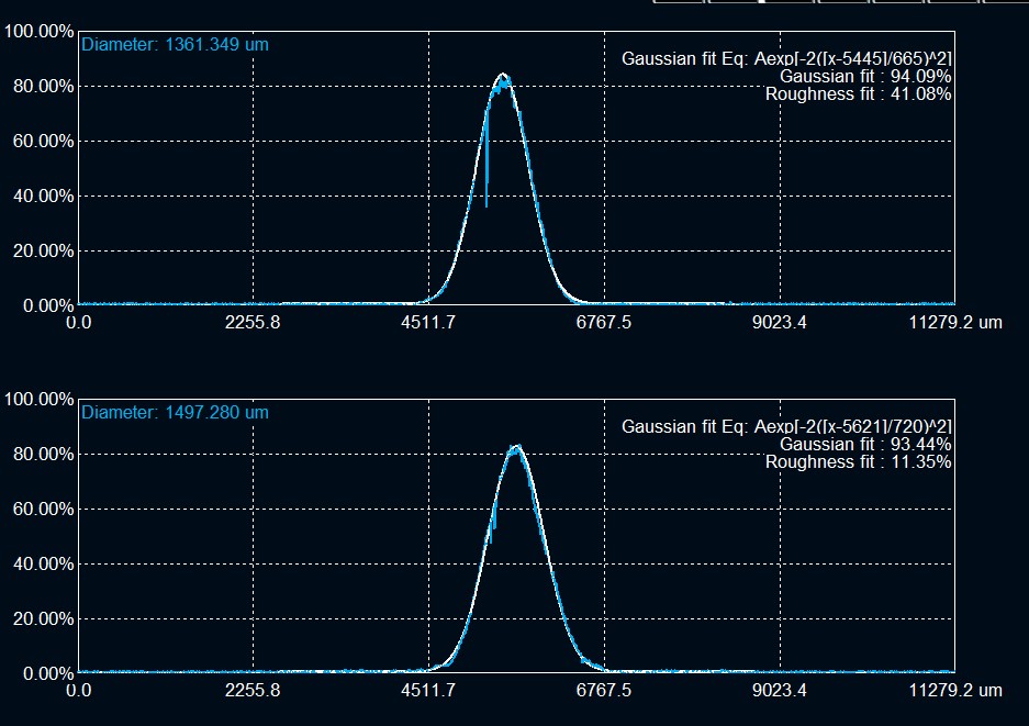
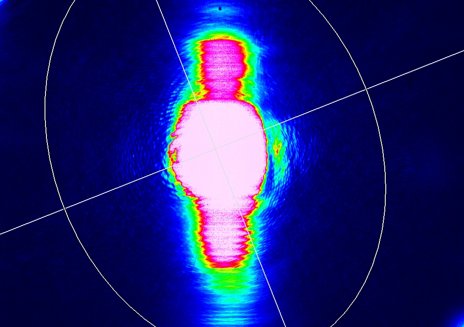
the CVBG is to be used at a small angle, the beam shape and spectrum after the PBS is attached.
After measuring the beam profile, a mirror was placed to direct all the power for fiber injection
power before the fiber is 13 mW and the power injected is 6.19 mW
|
| Attachment 1: CVBG.jpg
|
 |
| Attachment 2: beamafterCVBG.jpg
|
 |
| Attachment 3: beamafterCVBG_Fit.jpg
|
 |
| Attachment 4: beamafterCVBG_saturated.jpg
|
 |
| Attachment 5: SpectrumafterCVBGzoom.png
|
 |
| Attachment 6: CVBG_Injection_Setup.jpg
|
 |
| Attachment 7: 20220722_CVBG_stretching.jpeg
|
 |
|
120
|
Fri Jul 22 18:25:31 2022 |
Manar Amer | Fixed | report | lasers and optics | detectors and electronics | software | Optical room | CELIA amplifier installation + chiller |
The software to control the CELIA amplifier is on the laptop that was placed in ThomX bunker.
I have placed it in the PLIC room next to the SBox table.
it is called 'Alphanov Control Software'
| Manar Amer wrote: |
|
Amplifier placed next to the pulsed laser on the table under the airflow
The output is in free space with height from the table of about 10 cm, note the injection height into the cavity is between 14 - 15 cm.
a power cable is placed but not plugged.
Connection to the computer is made using USB B on amplifier to USB A (note need a longer cable, the available on is too short)
The cooling, to be connected to an outside chiller, will use the bottom one shown in the image attached.
The two water tubes, from chiller to amplifier, has been marked. The size of the tubes from the amplifier fit inside the tubes from the chiller.
| Manar Amer wrote: |
|
The amplifier was installed on the optical table next to SBox table.
The CVBG that will be used for stretching before amplification needs cleaning (they are very fragile, 'ask victor for best method')
The software to drive the diodes of the amplifier we have is not the compatible one.
|
|
|
|
129
|
Fri Aug 19 16:02:33 2022 |
Manar Amer | Fixed | report | lasers and optics | detectors and electronics | software | Optical room | CELIA amplifier installation + chiller |
Closing series
| Manar Amer wrote: |
|
The software to control the CELIA amplifier is on the laptop that was placed in ThomX bunker.
I have placed it in the PLIC room next to the SBox table.
it is called 'Alphanov Control Software'
| Manar Amer wrote: |
|
Amplifier placed next to the pulsed laser on the table under the airflow
The output is in free space with height from the table of about 10 cm, note the injection height into the cavity is between 14 - 15 cm.
a power cable is placed but not plugged.
Connection to the computer is made using USB B on amplifier to USB A (note need a longer cable, the available on is too short)
The cooling, to be connected to an outside chiller, will use the bottom one shown in the image attached.
The two water tubes, from chiller to amplifier, has been marked. The size of the tubes from the amplifier fit inside the tubes from the chiller.
| Manar Amer wrote: |
|
The amplifier was installed on the optical table next to SBox table.
The CVBG that will be used for stretching before amplification needs cleaning (they are very fragile, 'ask victor for best method')
The software to drive the diodes of the amplifier we have is not the compatible one.
|
|
|
|
|
130
|
Fri Aug 19 16:03:17 2022 |
Manar Amer | Fixed | report | lasers and optics | detectors and electronics | software | Optical room | Alignment / Table setup |
closing series
| Manar Amer wrote: |
|
The current setup of the optical table attached.
The cavity is aligned and the lock of the fundamental mode has been attempted, but the mode is drifting too quickly to be able to follow.
I have placed the cavity under vacuum for a better stability.
a simple telescope for the CW was adjusted to having 2 lenses of 300 mm placed ~ 250 mm away from the colimator and 200 mm lens placed after it with 510 mm.
|
|
|
131
|
Fri Aug 19 16:03:40 2022 |
Manar Amer | Fixed | report | lasers and optics | detectors and electronics | software | Optical room | CVBG stretching / Fiber Injection |
closing series
| Manar Amer wrote: |
|
Before injecting into the amplifier, the pulse needs to be stretched using a CVBG, type attached.
the CVBG is to be used at a small angle, the beam shape and spectrum after the PBS is attached.
After measuring the beam profile, a mirror was placed to direct all the power for fiber injection
power before the fiber is 13 mW and the power injected is 6.19 mW
|
|
|
64
|
Mon Jul 5 14:14:01 2021 |
Manar Amer | Fixed | report | lasers and optics | detectors and electronics | Optical room | OEwaves CW Laser - Phase Noise |
- We started measuring the phase noise on the OEwaves CW laser.
- Class 3b
- wavelength 1.5 um
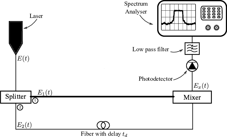
- The procedure is done using self coupling of the laser
- splitter 50%-50%\
- delay line 100 m
- all fibers are PM type (polarity maintained)
- Photodetector is "lab buddy", very fast diode.
- Note: différance from schematic (we did not use a low pass filter)
|
| Attachment 1: 20210207_OEwaves_laser.jpg
|
 |
| Attachment 2: 20210207_Self_coupling_setup.jpg
|
 |
| Attachment 3: Schematic-setup-for-optical-delayed-self-coupling-detection.png
|
 |
|
65
|
Mon Jul 5 14:40:57 2021 |
Manar Amer | Fixed | report | lasers and optics | detectors and electronics | Optical room | OEwaves CW Laser - Phase Noise |
a correction on the wavelength of the laser it is 1030 um
| Manar Amer wrote: |
- We started measuring the phase noise on the OEwaves CW laser.
- Class 3b
- wavelength 1.5 um
- The procedure is done using self coupling of the laser
- splitter 50%-50%\
- delay line 100 m
- all fibers are PM type (polarity maintained)
- Photodetector is "lab buddy", very fast diode.
- Note: différance from schematic (we did not use a low pass filter)
|
|
|
66
|
Mon Jul 5 14:46:44 2021 |
Manar Amer | Fixed | report | lasers and optics | detectors and electronics | Optical room | OEwaves CW Laser - Phase Noise |
correction on unit 1030 nm
| Manar Amer wrote: |
|
a correction on the wavelength of the laser it is 1030 um
| Manar Amer wrote: |
- We started measuring the phase noise on the OEwaves CW laser.
- Class 3b
- wavelength 1.5 um
- The procedure is done using self coupling of the laser
- splitter 50%-50%\
- delay line 100 m
- all fibers are PM type (polarity maintained)
- Photodetector is "lab buddy", very fast diode.
- Note: différance from schematic (we did not use a low pass filter)
|
|
|
|
106
|
Wed Jul 6 19:57:17 2022 |
Manar Amer | Fixed | report | lasers and optics | detectors and electronics | Optical room | 2 Mirror Setup @ 216.6 MHz |
The SBox cavity setup was changed to have only 2 mirrors M1 plane and M2 spherical, both from ThomX
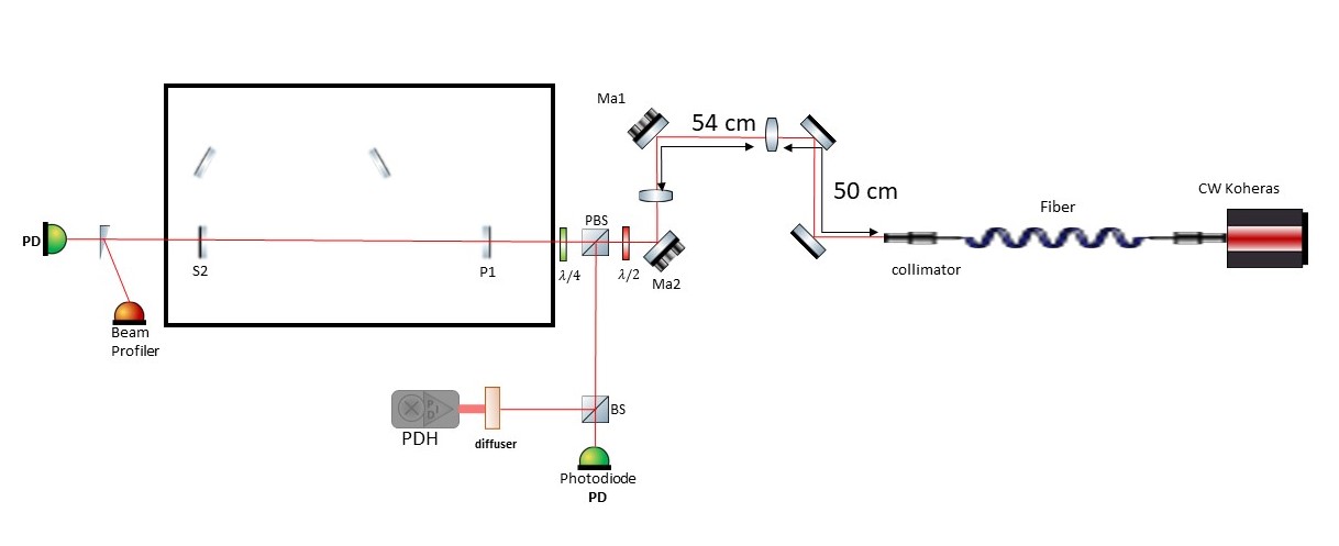
Distance between the mirror ~ 72 cm , increased from 70 cm to take into account the thickness of the ThomX mirrors
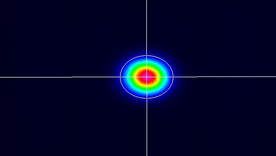
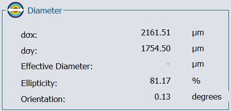
Two lenses (300 mm @ 50 cm , 200 @ 104 cm) were placed to have the beam radius ~ 0.55 mm.
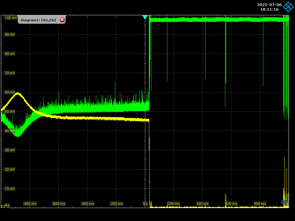
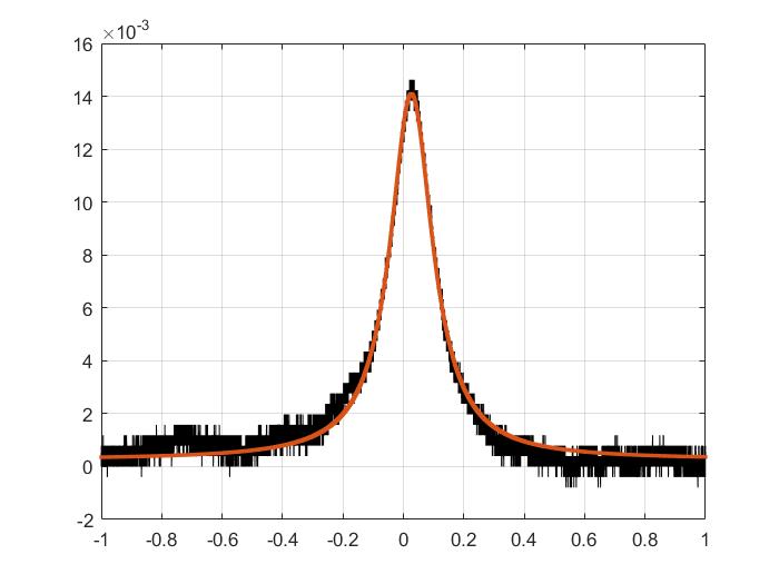
The cavity was locked with a coupling of 60 %, for Finesse measurement the sweep was taken over 100 KHz of 2 seconds.
FSR ~ 210.00 MHz, line width ~ 8.56 KHz, Finesse ~ 24 500 .
|
| Attachment 1: 20220706_Setup.jpg
|
 |
| Attachment 2: Screenshot_2022-07-06_1_181116.png
|
 |
| Attachment 3: Finesse_Fit.jpg
|
 |
| Attachment 4: 00mode.jpg
|
 |
| Attachment 5: 00mode_diameter.jpg
|
 |
|
109
|
Fri Jul 8 17:48:48 2022 |
Manar Amer | Fixed | report | lasers and optics | detectors and electronics | Optical room | 2 Mirror Setup @ 216.6 MHz |
The cavity was realigned using irises instead of pinholes, gave a better alignment.
The inside of the box, the spherical and the injection mirror were cleaned and placed back inside the box.
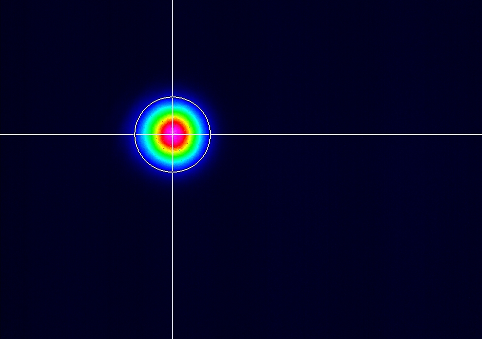
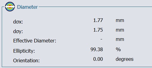
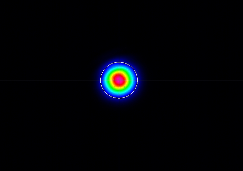
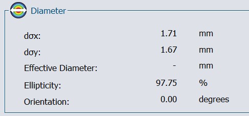
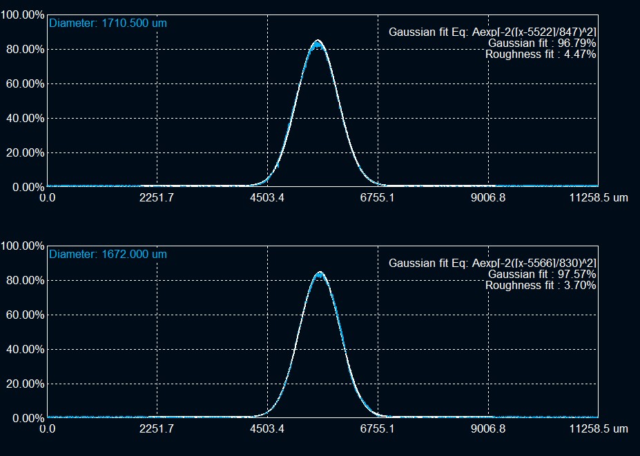
we see beating of fundamental mode, previously at the transmission point we placed a wedge to split the beam which resulted in an elliptical mode
we removed it and placed a very thin beam splitter, the beam is circular now.
The cavity was locked in air at a coupling of ~ 60-70 %
Finesse and line width measured five readings with a Finesse average 25095.08884 of a Gain ~ 8000
FWHM (KHz) = 8.2928
Finesse = 25323.0544
FWHM (KHz) = 7.9202
Finesse = 26514.4395
FWHM (KHz) = 8.5834
Finesse = 24465.8636
FWHM (KHz) = 8.4571
Finesse = 24831.2419
FWHM (KHz) = 8.6275
Finesse = 24340.8448
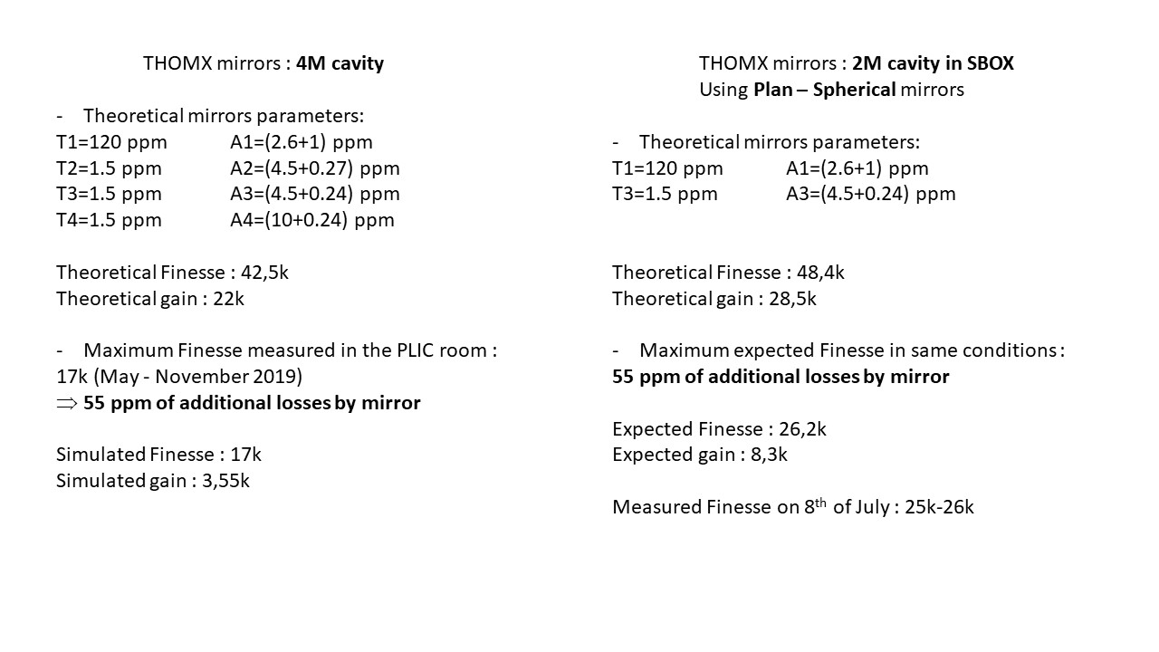
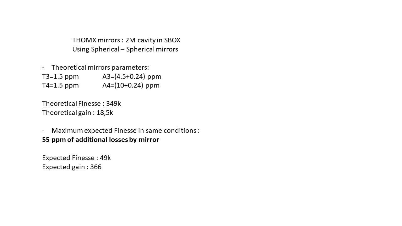
Theoretical and expected Finesse for the 2 mirror setup with the losses is calculated by Ronic for comparison between four and 2 mirror setup.
| Manar Amer wrote: |
|
The SBox cavity setup was changed to have only 2 mirrors M1 plane and M2 spherical, both from ThomX
Distance between the mirror ~ 72 cm , increased from 70 cm to take into account the thickness of the ThomX mirrors
Two lenses (300 mm @ 50 cm , 200 @ 104 cm) were placed to have the beam radius ~ 0.55 mm.
The cavity was locked with a coupling of 60 %, for Finesse measurement the sweep was taken over 100 KHz of 2 seconds.
FSR ~ 210.00 MHz, line width ~ 8.56 KHz, Finesse ~ 24 500 .
|
|
| Attachment 1: 00mode.jpg
|
 |
| Attachment 2: 00mode_diameter.jpg
|
 |
| Attachment 3: Screenshot_2022-07-08_0_164115.png
|
 |
| Attachment 4: Slide1.JPG
|
 |
| Attachment 5: Slide2.JPG
|
 |
|
110
|
Fri Jul 8 19:37:24 2022 |
Manar Amer | Fixed | report | lasers and optics | detectors and electronics | Optical room | 2 Mirror Setup @ 216.6 MHz |
Update for Finesse measurement, The cavity was put under vacuum ~ 1.1*10^-1 mbar
and the alignment and coupling improved.
FSR = 210.1 MHz
Average Finesse = 25686.46222
FWHM (KHz) = 8.2387
Finesse = 25501.5659
FWHM (KHz) = 8.2028
Finesse = 25613.2858
FWHM (KHz) = 8.0978
Finesse = 25945.3289
FWHM (KHz) = 8.1744
Finesse = 25702.3142
FWHM (KHz) = 8.1847
Finesse = 25669.8163
Concluded from Ronic's calculations, this could be the maximum finesse we might be able to obtain with this setup
with Gain ~ 8000
On Monday we adjust the frequency to match 2160.66 MHz and lock the Pulsed,
at the same time start we start with the CELIA amplifier.
| Manar Amer wrote: |
|
The cavity was realigned using irises instead of pinholes, gave a better alignment.
The inside of the box, the spherical and the injection mirror were cleaned and placed back inside the box.
we see beating of fundamental mode, previously at the transmission point we placed a wedge to split the beam which resulted in an elliptical mode
we removed it and placed a very thin beam splitter, the beam is circular now.
The cavity was locked in air at a coupling of ~ 60-70 %
Finesse and line width measured five readings with a Finesse average 25095.08884 of a Gain ~ 8000
FWHM (KHz) = 8.2928
Finesse = 25323.0544
FWHM (KHz) = 7.9202
Finesse = 26514.4395
FWHM (KHz) = 8.5834
Finesse = 24465.8636
FWHM (KHz) = 8.4571
Finesse = 24831.2419
FWHM (KHz) = 8.6275
Finesse = 24340.8448
Theoretical and expected Finesse for the 2 mirror setup with the losses is calculated by Ronic for comparison between four and 2 mirror setup.
| Manar Amer wrote: |
|
The SBox cavity setup was changed to have only 2 mirrors M1 plane and M2 spherical, both from ThomX
Distance between the mirror ~ 72 cm , increased from 70 cm to take into account the thickness of the ThomX mirrors
Two lenses (300 mm @ 50 cm , 200 @ 104 cm) were placed to have the beam radius ~ 0.55 mm.
The cavity was locked with a coupling of 60 %, for Finesse measurement the sweep was taken over 100 KHz of 2 seconds.
FSR ~ 210.00 MHz, line width ~ 8.56 KHz, Finesse ~ 24 500 .
|
|
|
| Attachment 1: Screenshot_2022-07-08_2_182405.png
|
 |
|
111
|
Tue Jul 12 10:07:05 2022 |
Manar Amer | Fixed | report | lasers and optics | detectors and electronics | Optical room | FSR change & Finesse Measurements |
The FSR of the 2 mirror (plan-spherical) Cavity was adjusted from 210 MHz to reach 216.643 MHz
it was done by having two reference irises, one at the injection point and one at the reflection
then changing the position of injection plan mirror to slightly closer distance and monitoring the reflection on the oscilloscope to be max.
The cavity modes were still seen, and we had to only improve the injection alignment after.
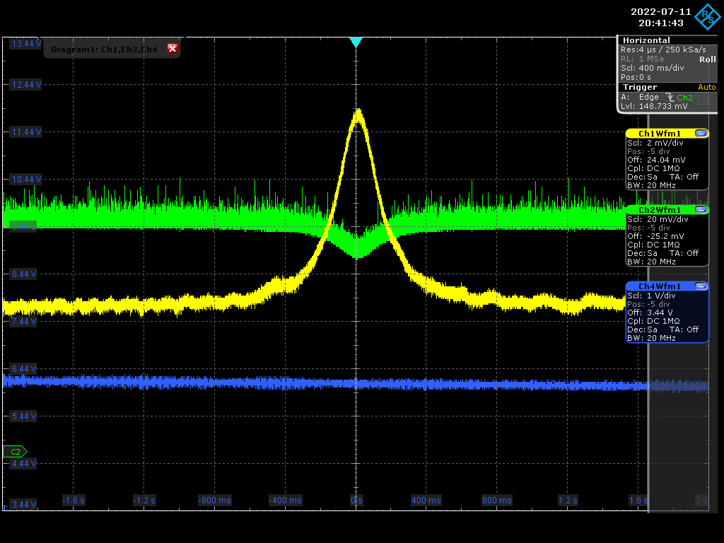
Me and Ronic locked in air and measured the Finesse, which was bigger by ~ 20%
average Finesse = 30208.53614
FWHM (KHz) = 7.0179
Finesse = 30869.9522
FWHM (KHz) = 7.1257
Finesse = 30403.005
FWHM (KHz) = 7.1287
Finesse = 30390.4014
FWHM (KHz) = 7.2884
Finesse = 29724.5531
FWHM (KHz) = 7.3055
Finesse = 29654.769
| Manar Amer wrote: |
|
Update for Finesse measurement, The cavity was put under vacuum ~ 1.1*10^-1 mbar
and the alignment and coupling improved.
FSR = 210.1 MHz
Average Finesse = 25686.46222
FWHM (KHz) = 8.2387
Finesse = 25501.5659
FWHM (KHz) = 8.2028
Finesse = 25613.2858
FWHM (KHz) = 8.0978
Finesse = 25945.3289
FWHM (KHz) = 8.1744
Finesse = 25702.3142
FWHM (KHz) = 8.1847
Finesse = 25669.8163
Concluded from Ronic's calculations, this could be the maximum finesse we might be able to obtain with this setup
with Gain ~ 8000
On Monday we adjust the frequency to match 2160.66 MHz and lock the Pulsed,
at the same time start we start with the CELIA amplifier.
| Manar Amer wrote: |
|
The cavity was realigned using irises instead of pinholes, gave a better alignment.
The inside of the box, the spherical and the injection mirror were cleaned and placed back inside the box.
we see beating of fundamental mode, previously at the transmission point we placed a wedge to split the beam which resulted in an elliptical mode
we removed it and placed a very thin beam splitter, the beam is circular now.
The cavity was locked in air at a coupling of ~ 60-70 %
Finesse and line width measured five readings with a Finesse average 25095.08884 of a Gain ~ 8000
FWHM (KHz) = 8.2928
Finesse = 25323.0544
FWHM (KHz) = 7.9202
Finesse = 26514.4395
FWHM (KHz) = 8.5834
Finesse = 24465.8636
FWHM (KHz) = 8.4571
Finesse = 24831.2419
FWHM (KHz) = 8.6275
Finesse = 24340.8448
Theoretical and expected Finesse for the 2 mirror setup with the losses is calculated by Ronic for comparison between four and 2 mirror setup.
| Manar Amer wrote: |
|
The SBox cavity setup was changed to have only 2 mirrors M1 plane and M2 spherical, both from ThomX
Distance between the mirror ~ 72 cm , increased from 70 cm to take into account the thickness of the ThomX mirrors
Two lenses (300 mm @ 50 cm , 200 @ 104 cm) were placed to have the beam radius ~ 0.55 mm.
The cavity was locked with a coupling of 60 %, for Finesse measurement the sweep was taken over 100 KHz of 2 seconds.
FSR ~ 210.00 MHz, line width ~ 8.56 KHz, Finesse ~ 24 500 .
|
|
|
|
| Attachment 1: 00mode.jpg
|
 |
| Attachment 2: 00mode_diameter.jpg
|
 |
| Attachment 3: 00mode_diameter_fit.jpg
|
 |
|
112
|
Tue Jul 12 10:19:30 2022 |
Manar Amer | Fixed | report | lasers and optics | detectors and electronics | Optical room | FSR change & Finesse Measurements |
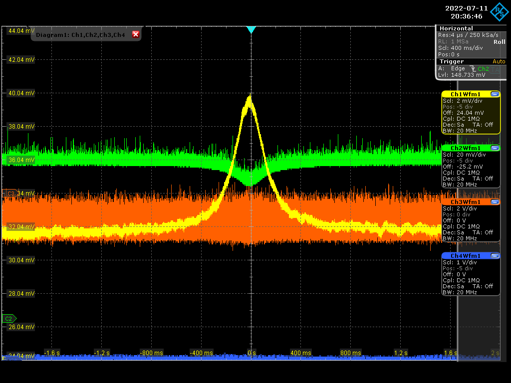
Yesterday evening the cavity was Vacuum pumped up to pressure of 5.5*10^-2 and locked
changed FSR to be 216.662 MHz and alignment a little and measured the Finesse
in Vacuum we have average Finesse = 30341.6265
FWHM (KHz) = 7.0592
Finesse = 30692.1961
FWHM (KHz) = 7.2186
Finesse = 30014.556
FWHM (KHz) = 7.1051
Finesse = 30493.7635
FWHM (KHz) = 7.1079
Finesse = 30481.9812
FWHM (KHz) = 7.1413
Finesse = 30339.2695
FWHM (KHz) = 7.1624
Finesse = 30249.776
FWHM (KHz) = 7.0239
Finesse = 30846.2719
FWHM (KHz) = 7.2614
Finesse = 29837.6477
FWHM (KHz) = 7.1935
Finesse = 30119.1768
| Manar Amer wrote: |
|
The FSR of the 2 mirror (plan-spherical) Cavity was adjusted from 210 MHz to reach 216.643 MHz
it was done by having two reference irises, one at the injection point and one at the reflection
then changing the position of injection plan mirror to slightly closer distance and monitoring the reflection on the oscilloscope to be max.
The cavity modes were still seen, and we had to only improve the injection alignment after.
Me and Ronic locked in air and measured the Finesse, which was bigger by ~ 20%
average Finesse = 30208.53614
FWHM (KHz) = 7.0179
Finesse = 30869.9522
FWHM (KHz) = 7.1257
Finesse = 30403.005
FWHM (KHz) = 7.1287
Finesse = 30390.4014
FWHM (KHz) = 7.2884
Finesse = 29724.5531
FWHM (KHz) = 7.3055
Finesse = 29654.769
| Manar Amer wrote: |
|
Update for Finesse measurement, The cavity was put under vacuum ~ 1.1*10^-1 mbar
and the alignment and coupling improved.
FSR = 210.1 MHz
Average Finesse = 25686.46222
FWHM (KHz) = 8.2387
Finesse = 25501.5659
FWHM (KHz) = 8.2028
Finesse = 25613.2858
FWHM (KHz) = 8.0978
Finesse = 25945.3289
FWHM (KHz) = 8.1744
Finesse = 25702.3142
FWHM (KHz) = 8.1847
Finesse = 25669.8163
Concluded from Ronic's calculations, this could be the maximum finesse we might be able to obtain with this setup
with Gain ~ 8000
On Monday we adjust the frequency to match 2160.66 MHz and lock the Pulsed,
at the same time start we start with the CELIA amplifier.
| Manar Amer wrote: |
|
The cavity was realigned using irises instead of pinholes, gave a better alignment.
The inside of the box, the spherical and the injection mirror were cleaned and placed back inside the box.
we see beating of fundamental mode, previously at the transmission point we placed a wedge to split the beam which resulted in an elliptical mode
we removed it and placed a very thin beam splitter, the beam is circular now.
The cavity was locked in air at a coupling of ~ 60-70 %
Finesse and line width measured five readings with a Finesse average 25095.08884 of a Gain ~ 8000
FWHM (KHz) = 8.2928
Finesse = 25323.0544
FWHM (KHz) = 7.9202
Finesse = 26514.4395
FWHM (KHz) = 8.5834
Finesse = 24465.8636
FWHM (KHz) = 8.4571
Finesse = 24831.2419
FWHM (KHz) = 8.6275
Finesse = 24340.8448
Theoretical and expected Finesse for the 2 mirror setup with the losses is calculated by Ronic for comparison between four and 2 mirror setup.
| Manar Amer wrote: |
|
The SBox cavity setup was changed to have only 2 mirrors M1 plane and M2 spherical, both from ThomX
Distance between the mirror ~ 72 cm , increased from 70 cm to take into account the thickness of the ThomX mirrors
Two lenses (300 mm @ 50 cm , 200 @ 104 cm) were placed to have the beam radius ~ 0.55 mm.
The cavity was locked with a coupling of 60 %, for Finesse measurement the sweep was taken over 100 KHz of 2 seconds.
FSR ~ 210.00 MHz, line width ~ 8.56 KHz, Finesse ~ 24 500 .
|
|
|
|
|
| Attachment 1: Screenshot_2022-07-11_1_204143.png
|
 |
| Attachment 2: Screenshot_2022-07-11_0_203646.png
|
 |
|
113
|
Tue Jul 12 14:41:55 2022 |
Manar Amer | Fixed | report | lasers and optics | detectors and electronics | Optical room | FSR change & Finesse Measurements |
a Finesse of 30k with the present mirrors :
T1=120 ppm ;A1=(2.6+1) ppm;
T2=1.5 ppm ;A2=(4.5+0.27) ppm;
corresponds to 39 ppm of additional losses for each mirror and a theoretical gain of about 11k.
| Manar Amer wrote: |
|
Yesterday evening the cavity was Vacuum pumped up to pressure of 5.5*10^-2 and locked
changed FSR to be 216.662 MHz and alignment a little and measured the Finesse
in Vacuum we have average Finesse = 30341.6265
FWHM (KHz) = 7.0592
Finesse = 30692.1961
FWHM (KHz) = 7.2186
Finesse = 30014.556
FWHM (KHz) = 7.1051
Finesse = 30493.7635
FWHM (KHz) = 7.1079
Finesse = 30481.9812
FWHM (KHz) = 7.1413
Finesse = 30339.2695
FWHM (KHz) = 7.1624
Finesse = 30249.776
FWHM (KHz) = 7.0239
Finesse = 30846.2719
FWHM (KHz) = 7.2614
Finesse = 29837.6477
FWHM (KHz) = 7.1935
Finesse = 30119.1768
| Manar Amer wrote: |
|
The FSR of the 2 mirror (plan-spherical) Cavity was adjusted from 210 MHz to reach 216.643 MHz
it was done by having two reference irises, one at the injection point and one at the reflection
then changing the position of injection plan mirror to slightly closer distance and monitoring the reflection on the oscilloscope to be max.
The cavity modes were still seen, and we had to only improve the injection alignment after.
Me and Ronic locked in air and measured the Finesse, which was bigger by ~ 20%
average Finesse = 30208.53614
FWHM (KHz) = 7.0179
Finesse = 30869.9522
FWHM (KHz) = 7.1257
Finesse = 30403.005
FWHM (KHz) = 7.1287
Finesse = 30390.4014
FWHM (KHz) = 7.2884
Finesse = 29724.5531
FWHM (KHz) = 7.3055
Finesse = 29654.769
| Manar Amer wrote: |
|
Update for Finesse measurement, The cavity was put under vacuum ~ 1.1*10^-1 mbar
and the alignment and coupling improved.
FSR = 210.1 MHz
Average Finesse = 25686.46222
FWHM (KHz) = 8.2387
Finesse = 25501.5659
FWHM (KHz) = 8.2028
Finesse = 25613.2858
FWHM (KHz) = 8.0978
Finesse = 25945.3289
FWHM (KHz) = 8.1744
Finesse = 25702.3142
FWHM (KHz) = 8.1847
Finesse = 25669.8163
Concluded from Ronic's calculations, this could be the maximum finesse we might be able to obtain with this setup
with Gain ~ 8000
On Monday we adjust the frequency to match 2160.66 MHz and lock the Pulsed,
at the same time start we start with the CELIA amplifier.
| Manar Amer wrote: |
|
The cavity was realigned using irises instead of pinholes, gave a better alignment.
The inside of the box, the spherical and the injection mirror were cleaned and placed back inside the box.
we see beating of fundamental mode, previously at the transmission point we placed a wedge to split the beam which resulted in an elliptical mode
we removed it and placed a very thin beam splitter, the beam is circular now.
The cavity was locked in air at a coupling of ~ 60-70 %
Finesse and line width measured five readings with a Finesse average 25095.08884 of a Gain ~ 8000
FWHM (KHz) = 8.2928
Finesse = 25323.0544
FWHM (KHz) = 7.9202
Finesse = 26514.4395
FWHM (KHz) = 8.5834
Finesse = 24465.8636
FWHM (KHz) = 8.4571
Finesse = 24831.2419
FWHM (KHz) = 8.6275
Finesse = 24340.8448
Theoretical and expected Finesse for the 2 mirror setup with the losses is calculated by Ronic for comparison between four and 2 mirror setup.
| Manar Amer wrote: |
|
The SBox cavity setup was changed to have only 2 mirrors M1 plane and M2 spherical, both from ThomX
Distance between the mirror ~ 72 cm , increased from 70 cm to take into account the thickness of the ThomX mirrors
Two lenses (300 mm @ 50 cm , 200 @ 104 cm) were placed to have the beam radius ~ 0.55 mm.
The cavity was locked with a coupling of 60 %, for Finesse measurement the sweep was taken over 100 KHz of 2 seconds.
FSR ~ 210.00 MHz, line width ~ 8.56 KHz, Finesse ~ 24 500 .
|
|
|
|
|
|
|
114
|
Tue Jul 12 18:53:55 2022 |
Manar Amer | Fixed | report | lasers and optics | detectors and electronics | Optical room | Installation of D-shaped mirror / Alignment |
To prepare for the amplifier. I installed the D-shapped mirrors after cleaning (using aceton and ethanol) between the cavity 2 mirrors.
Before closing, I observed the back reflection from M1 (injection mirror). both the injection and reflection lines were off, due to that there was an internal reflection hitting the walls of the cavity.
I tried to correct it by slightly adjusting on M1 without losing the mode, but unfortunately we lost it.
Tried to go back to the original position using the reflection iris reference, with no success.
Cavity axis is lost, and we need to align again.
| Manar Amer wrote: |
|
a Finesse of 30k with the present mirrors :
T1=120 ppm ;A1=(2.6+1) ppm;
T2=1.5 ppm ;A2=(4.5+0.27) ppm;
corresponds to 39 ppm of additional losses for each mirror and a theoretical gain of about 11k.
| Manar Amer wrote: |
|
Yesterday evening the cavity was Vacuum pumped up to pressure of 5.5*10^-2 and locked
changed FSR to be 216.662 MHz and alignment a little and measured the Finesse
in Vacuum we have average Finesse = 30341.6265
FWHM (KHz) = 7.0592
Finesse = 30692.1961
FWHM (KHz) = 7.2186
Finesse = 30014.556
FWHM (KHz) = 7.1051
Finesse = 30493.7635
FWHM (KHz) = 7.1079
Finesse = 30481.9812
FWHM (KHz) = 7.1413
Finesse = 30339.2695
FWHM (KHz) = 7.1624
Finesse = 30249.776
FWHM (KHz) = 7.0239
Finesse = 30846.2719
FWHM (KHz) = 7.2614
Finesse = 29837.6477
FWHM (KHz) = 7.1935
Finesse = 30119.1768
| Manar Amer wrote: |
|
The FSR of the 2 mirror (plan-spherical) Cavity was adjusted from 210 MHz to reach 216.643 MHz
it was done by having two reference irises, one at the injection point and one at the reflection
then changing the position of injection plan mirror to slightly closer distance and monitoring the reflection on the oscilloscope to be max.
The cavity modes were still seen, and we had to only improve the injection alignment after.
Me and Ronic locked in air and measured the Finesse, which was bigger by ~ 20%
average Finesse = 30208.53614
FWHM (KHz) = 7.0179
Finesse = 30869.9522
FWHM (KHz) = 7.1257
Finesse = 30403.005
FWHM (KHz) = 7.1287
Finesse = 30390.4014
FWHM (KHz) = 7.2884
Finesse = 29724.5531
FWHM (KHz) = 7.3055
Finesse = 29654.769
| Manar Amer wrote: |
|
Update for Finesse measurement, The cavity was put under vacuum ~ 1.1*10^-1 mbar
and the alignment and coupling improved.
FSR = 210.1 MHz
Average Finesse = 25686.46222
FWHM (KHz) = 8.2387
Finesse = 25501.5659
FWHM (KHz) = 8.2028
Finesse = 25613.2858
FWHM (KHz) = 8.0978
Finesse = 25945.3289
FWHM (KHz) = 8.1744
Finesse = 25702.3142
FWHM (KHz) = 8.1847
Finesse = 25669.8163
Concluded from Ronic's calculations, this could be the maximum finesse we might be able to obtain with this setup
with Gain ~ 8000
On Monday we adjust the frequency to match 2160.66 MHz and lock the Pulsed,
at the same time start we start with the CELIA amplifier.
| Manar Amer wrote: |
|
The cavity was realigned using irises instead of pinholes, gave a better alignment.
The inside of the box, the spherical and the injection mirror were cleaned and placed back inside the box.
we see beating of fundamental mode, previously at the transmission point we placed a wedge to split the beam which resulted in an elliptical mode
we removed it and placed a very thin beam splitter, the beam is circular now.
The cavity was locked in air at a coupling of ~ 60-70 %
Finesse and line width measured five readings with a Finesse average 25095.08884 of a Gain ~ 8000
FWHM (KHz) = 8.2928
Finesse = 25323.0544
FWHM (KHz) = 7.9202
Finesse = 26514.4395
FWHM (KHz) = 8.5834
Finesse = 24465.8636
FWHM (KHz) = 8.4571
Finesse = 24831.2419
FWHM (KHz) = 8.6275
Finesse = 24340.8448
Theoretical and expected Finesse for the 2 mirror setup with the losses is calculated by Ronic for comparison between four and 2 mirror setup.
| Manar Amer wrote: |
|
The SBox cavity setup was changed to have only 2 mirrors M1 plane and M2 spherical, both from ThomX
Distance between the mirror ~ 72 cm , increased from 70 cm to take into account the thickness of the ThomX mirrors
Two lenses (300 mm @ 50 cm , 200 @ 104 cm) were placed to have the beam radius ~ 0.55 mm.
The cavity was locked with a coupling of 60 %, for Finesse measurement the sweep was taken over 100 KHz of 2 seconds.
FSR ~ 210.00 MHz, line width ~ 8.56 KHz, Finesse ~ 24 500 .
|
|
|
|
|
|
|
|
117
|
Fri Jul 22 17:10:06 2022 |
Manar Amer | Fixed | report | lasers and optics | detectors and electronics | Optical room | Installation of D-shaped mirror / Alignment |
The D-shaped mirrors are installed properly and not cutting the path of the beam.
The cavity has been aligned again and 00 modes beating observed, and external reference points has been placed.
| Manar Amer wrote: |
|
To prepare for the amplifier. I installed the D-shapped mirrors after cleaning (using aceton and ethanol) between the cavity 2 mirrors.
Before closing, I observed the back reflection from M1 (injection mirror). both the injection and reflection lines were off, due to that there was an internal reflection hitting the walls of the cavity.
I tried to correct it by slightly adjusting on M1 without losing the mode, but unfortunately we lost it.
Tried to go back to the original position using the reflection iris reference, with no success.
Cavity axis is lost, and we need to align again.
| Manar Amer wrote: |
|
a Finesse of 30k with the present mirrors :
T1=120 ppm ;A1=(2.6+1) ppm;
T2=1.5 ppm ;A2=(4.5+0.27) ppm;
corresponds to 39 ppm of additional losses for each mirror and a theoretical gain of about 11k.
| Manar Amer wrote: |
|
Yesterday evening the cavity was Vacuum pumped up to pressure of 5.5*10^-2 and locked
changed FSR to be 216.662 MHz and alignment a little and measured the Finesse
in Vacuum we have average Finesse = 30341.6265
FWHM (KHz) = 7.0592
Finesse = 30692.1961
FWHM (KHz) = 7.2186
Finesse = 30014.556
FWHM (KHz) = 7.1051
Finesse = 30493.7635
FWHM (KHz) = 7.1079
Finesse = 30481.9812
FWHM (KHz) = 7.1413
Finesse = 30339.2695
FWHM (KHz) = 7.1624
Finesse = 30249.776
FWHM (KHz) = 7.0239
Finesse = 30846.2719
FWHM (KHz) = 7.2614
Finesse = 29837.6477
FWHM (KHz) = 7.1935
Finesse = 30119.1768
| Manar Amer wrote: |
|
The FSR of the 2 mirror (plan-spherical) Cavity was adjusted from 210 MHz to reach 216.643 MHz
it was done by having two reference irises, one at the injection point and one at the reflection
then changing the position of injection plan mirror to slightly closer distance and monitoring the reflection on the oscilloscope to be max.
The cavity modes were still seen, and we had to only improve the injection alignment after.
Me and Ronic locked in air and measured the Finesse, which was bigger by ~ 20%
average Finesse = 30208.53614
FWHM (KHz) = 7.0179
Finesse = 30869.9522
FWHM (KHz) = 7.1257
Finesse = 30403.005
FWHM (KHz) = 7.1287
Finesse = 30390.4014
FWHM (KHz) = 7.2884
Finesse = 29724.5531
FWHM (KHz) = 7.3055
Finesse = 29654.769
| Manar Amer wrote: |
|
Update for Finesse measurement, The cavity was put under vacuum ~ 1.1*10^-1 mbar
and the alignment and coupling improved.
FSR = 210.1 MHz
Average Finesse = 25686.46222
FWHM (KHz) = 8.2387
Finesse = 25501.5659
FWHM (KHz) = 8.2028
Finesse = 25613.2858
FWHM (KHz) = 8.0978
Finesse = 25945.3289
FWHM (KHz) = 8.1744
Finesse = 25702.3142
FWHM (KHz) = 8.1847
Finesse = 25669.8163
Concluded from Ronic's calculations, this could be the maximum finesse we might be able to obtain with this setup
with Gain ~ 8000
On Monday we adjust the frequency to match 2160.66 MHz and lock the Pulsed,
at the same time start we start with the CELIA amplifier.
| Manar Amer wrote: |
|
The cavity was realigned using irises instead of pinholes, gave a better alignment.
The inside of the box, the spherical and the injection mirror were cleaned and placed back inside the box.
we see beating of fundamental mode, previously at the transmission point we placed a wedge to split the beam which resulted in an elliptical mode
we removed it and placed a very thin beam splitter, the beam is circular now.
The cavity was locked in air at a coupling of ~ 60-70 %
Finesse and line width measured five readings with a Finesse average 25095.08884 of a Gain ~ 8000
FWHM (KHz) = 8.2928
Finesse = 25323.0544
FWHM (KHz) = 7.9202
Finesse = 26514.4395
FWHM (KHz) = 8.5834
Finesse = 24465.8636
FWHM (KHz) = 8.4571
Finesse = 24831.2419
FWHM (KHz) = 8.6275
Finesse = 24340.8448
Theoretical and expected Finesse for the 2 mirror setup with the losses is calculated by Ronic for comparison between four and 2 mirror setup.
| Manar Amer wrote: |
|
The SBox cavity setup was changed to have only 2 mirrors M1 plane and M2 spherical, both from ThomX
Distance between the mirror ~ 72 cm , increased from 70 cm to take into account the thickness of the ThomX mirrors
Two lenses (300 mm @ 50 cm , 200 @ 104 cm) were placed to have the beam radius ~ 0.55 mm.
The cavity was locked with a coupling of 60 %, for Finesse measurement the sweep was taken over 100 KHz of 2 seconds.
FSR ~ 210.00 MHz, line width ~ 8.56 KHz, Finesse ~ 24 500 .
|
|
|
|
|
|
|
|
|
126
|
Thu Aug 11 19:27:09 2022 |
Ronic Chiche | Fixed | info | lasers and optics | detectors and electronics | Optical room | Koheras CW laser lock on FP cavity |
I locked the Koheras CW on the FP cavity but the lock was pretty noisy and very difficult to acquire.
I tried to produce some modulation sidebands close to 216MHz to measure the Finesse but the power loss was very small so, the signal to extract the Finesse would be unreadable !
(generator voltage was at maximum Vout = 0.5Vrms on 50 ohms... is it normal ? or the used 10GHz EOM suffers some problems ?)
At one moment, I lost the lock and was not able to find it again... it seems the Koheras is too noisy for this cavity (may be is it a good news for the Finesse ?).
Tomorrow, I will try to use the OEwave + amplifier to lock the cavity.
|