| ID |
Date |
Author |
Status |
Type |
Category |
Location |
Title |
|
57
|
Thu Feb 6 16:58:57 2020 |
Loïc Amoudry | Fixed | report | lasers and optics | Optical room | Power up to 48kW crater effect again |
As we said, after glow discharge and spin coater we recovered a low power finesse ~23000 (aligning away from the M1 crater).
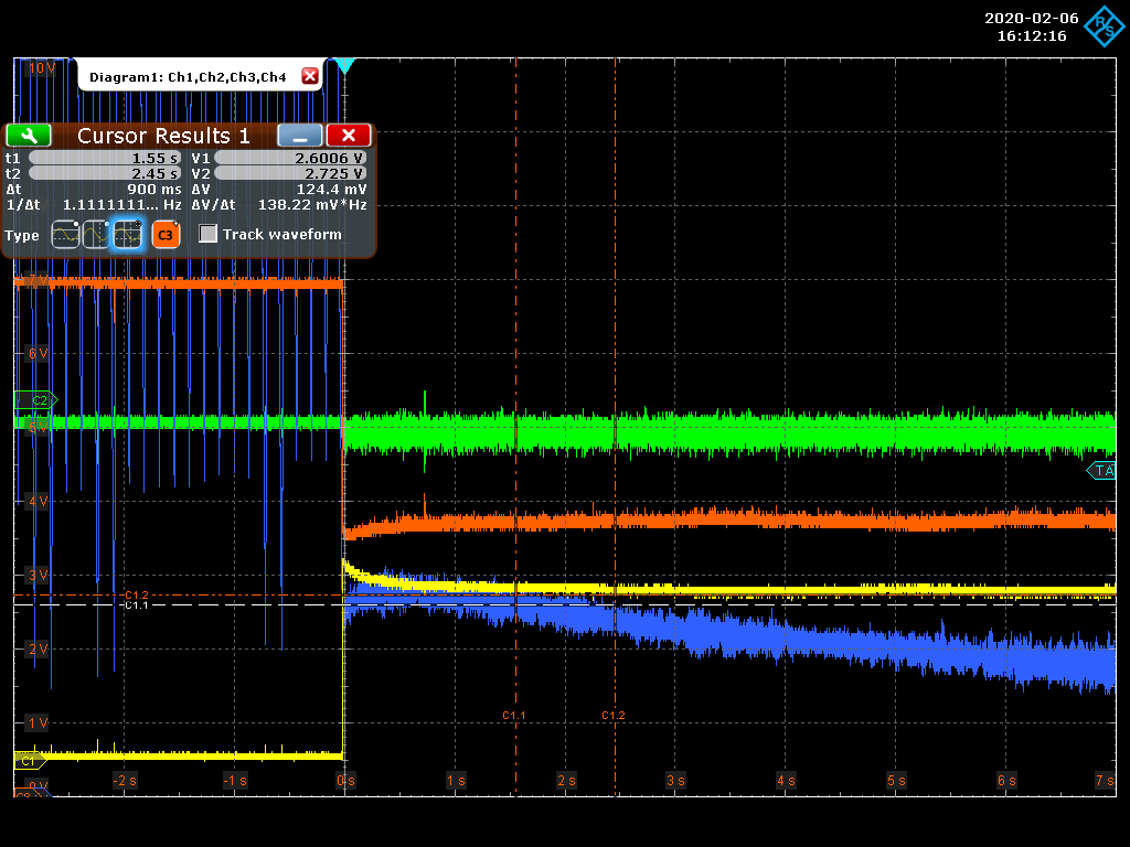
Today, we have made some power up to 48kW (3A on 3rd stage). At this power, there was no important effect on the transmission which can be compared with the coupling (see image "3A_136mWtrans"). We waited ~20min without aligning and the power dropped slowly (misalignment) to 39kW.
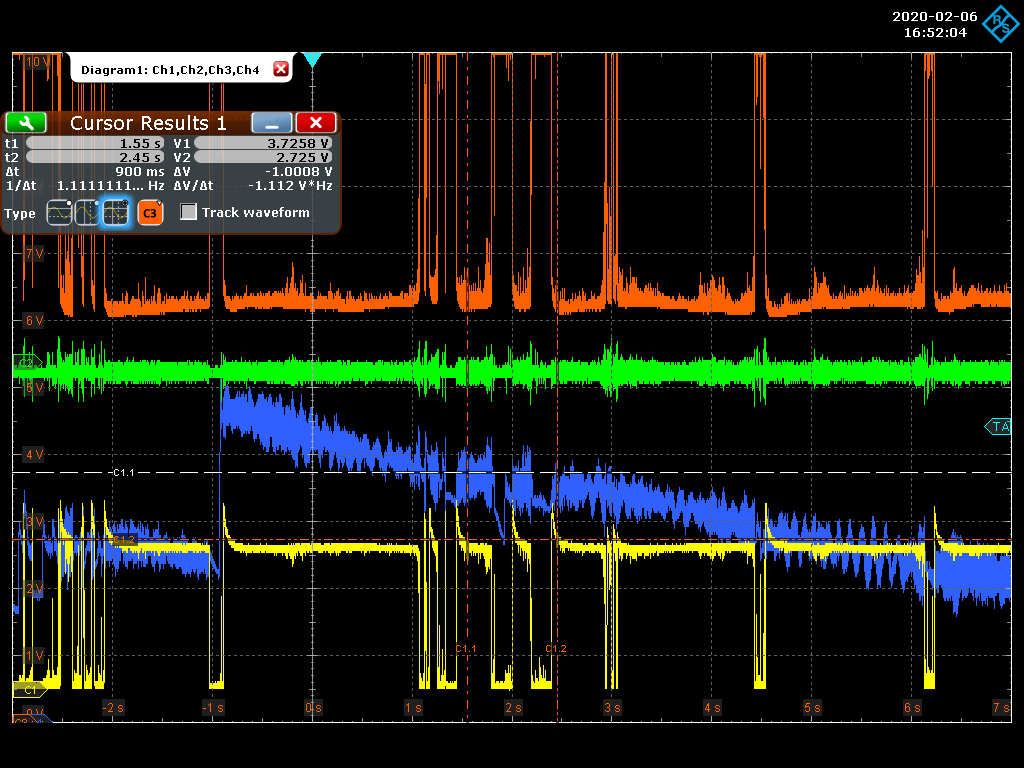
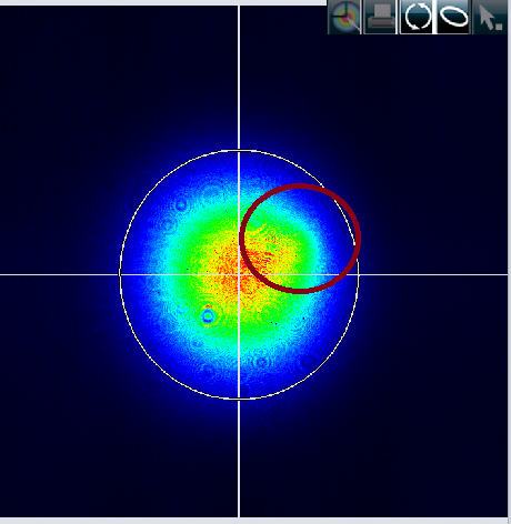
Then we increased the amplifier power to 4A and the power went up to 44kW. At this moment, the strange transmission behavior that we observed before mirror crater, appeared again (see image "4A_126mWtrans"). We also observed a mode deformation with the camera, see image "mode_strange". This shape was not depend of the camera/filter rotation angle and still appear with another camera.
| Loïc Amoudry wrote: |
|
The mirrors went in the cavity the 28th of november (We did several power up to 30kW stored and only one to 40kW then the power went down to 2kW during the run).
Microscope study shows that mirrors get some dust during the handling [travel from microscope to SBOX --> installation --> in SBOX for +1month and power up --> travel to microscope].
Almost all of these dusts can be removed with cleaning.
There is only one important difference between 28th of november and today, a large spot on M1.
|
|
| Attachment 1: 3A_136mWtrans.png
|
 |
| Attachment 2: 4A_126mWtrans.png
|
 |
| Attachment 3: mode_strange.png
|
 |
|
60
|
Wed Dec 16 12:36:37 2020 |
Loïc Amoudry | Fixed | report | lasers and optics | Optical room | Mirror's cleaning and microscope imaging |
On 10th of december 2020 we cleaned the SBOX mirrors and took microscope images (the name of the images indicates what they are).
There are 7 mirror, the initial M1 (spot in the center), M2 (spot on the edge), M3 and M4 which made the 200-400kW and the M2, M3 and M4 SPARE. The difference we make between M3 and M4 SPARE is the number on the box (11 or 13).
We used 3 different cleaning methods : 1st, one spin coater on HR, 2nd one, tissu wipe on AR (wipe with the optical tissu and isoprop) or 3rd one, mirror wiped on tissue (put isoprop on tissu and press AR face of the mirror doing "8" shape 3 times).
The second method is far les efficient as a cleaning method. The image "M3_M4_spare_11_after_cleaning_back.tif " shows the traces let by it and removed by the 3rd method on image "M3_M4_spare_11_after_cleaning_back_second_time_on_tissu.tif".
We can also notice that the spin coater let some trace on the HR face, round shaped, see Image "M3_M4_spare_13_after_cleaning_back.tif". We can propose to use the third method with Acetone on HR face before using spin coater to remove oil or organic particles.
It also lets a trace on the AR face, this is why we clean the AR face with the 2nd method after cleaning it with the spin coater.
Note : The position of the mirrors in the microscope is always the same here. Meaning mirrors are directed so that the arrow (which shows the HR face and is placed on the side of the mirror) is placed on the top of the images. |
| Attachment 1: M1_before_cleaning.tif
|
| Attachment 2: M1_after_cleaning.tif
|
| Attachment 3: M2_after_cleaning.tif
|
| Attachment 4: M3_after_cleaning.tif
|
| Attachment 5: M4_after_cleaning.tif
|
| Attachment 6: M2_spare_before_cleaning.tif
|
| Attachment 7: M2_spare_after_cleaning.tif
|
| Attachment 8: M2_spare_after_cleaning_back.tif
|
| Attachment 9: M3_M4_spare_11_before_cleaning.tif
|
| Attachment 10: M3_M4_spare_11_after_cleaning_back.tif
|
| Attachment 11: M3_M4_spare_11_after_cleaning_back_second_time_on_tissu.tif
|
| Attachment 12: M3_M4_spare_13_before_cleaning.tif
|
| Attachment 13: M3_M4_spare_13_after_cleaning.tif
|
| Attachment 14: M3_M4_spare_13_after_cleaning_back.tif
|
|
61
|
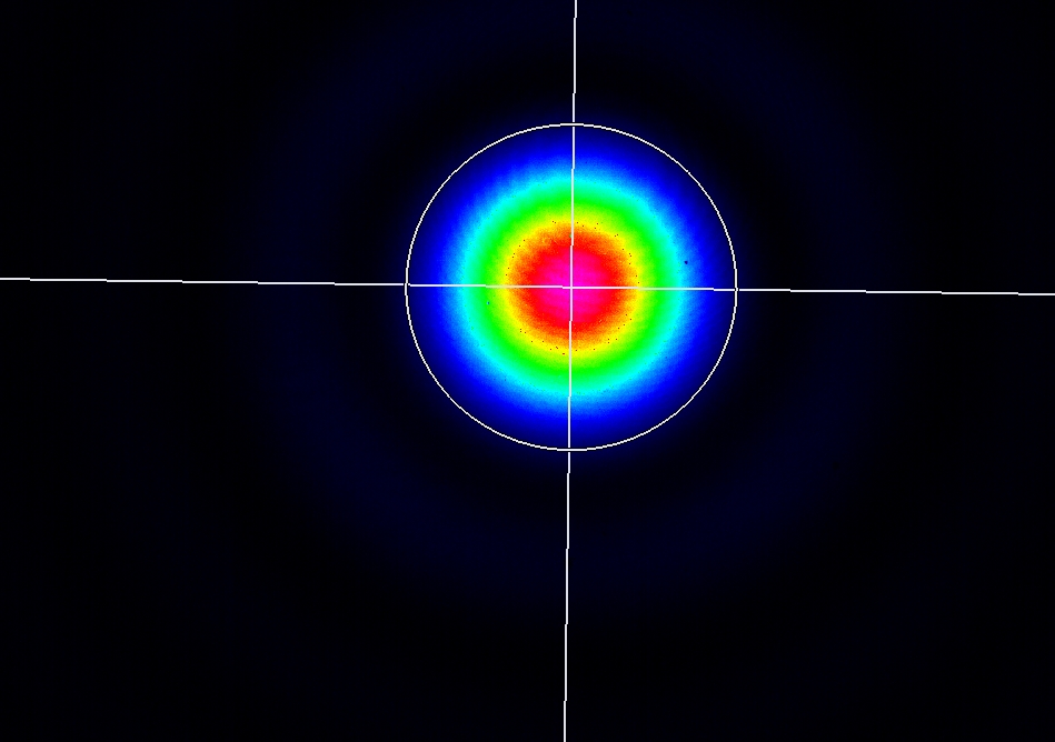
Tue Jan 5 12:38:04 2021 |
Manar Amer | Fixed | report | lasers and optics | Optical room | Transmission Measurements for the Mirrors. |
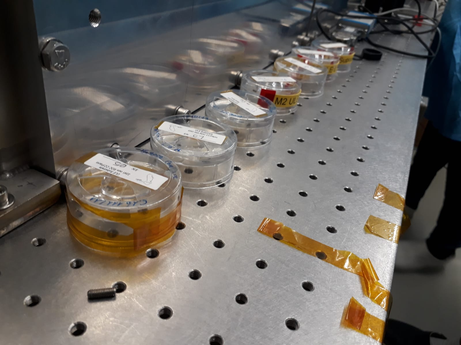
- Thursday 10 December 2020: First Test Measurement - Inside Box
- The transmission ( T ) for the mirrors of SBOX and ThomX was measured over a range from the center of the mirror up to 5mm.
-
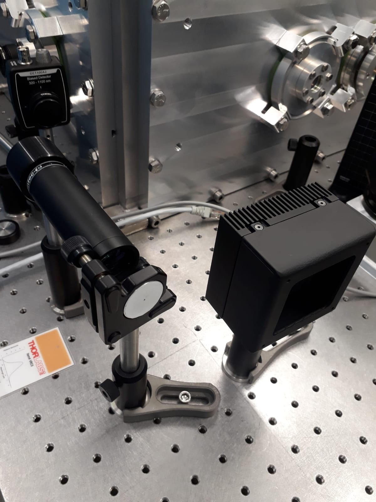
- The first setup was initially done while the mirrorr is installed inside the metal box, when measuring T we observe that there is an erregular change in the power measured as we move azay from the center of the mirror, this was due to reflection of light inside the box. The reflection from the mirror was reflected on the metal inside the box and it was measured by the power meter.
(so for this setup we only took measrements for T along the center of the mirror)
The file stating the measurements is : Test Cavity _ Mirrors transmission _ Inside box
=======================================================================
- Tuesday 15 December 2020 : Second Test - Outside Box
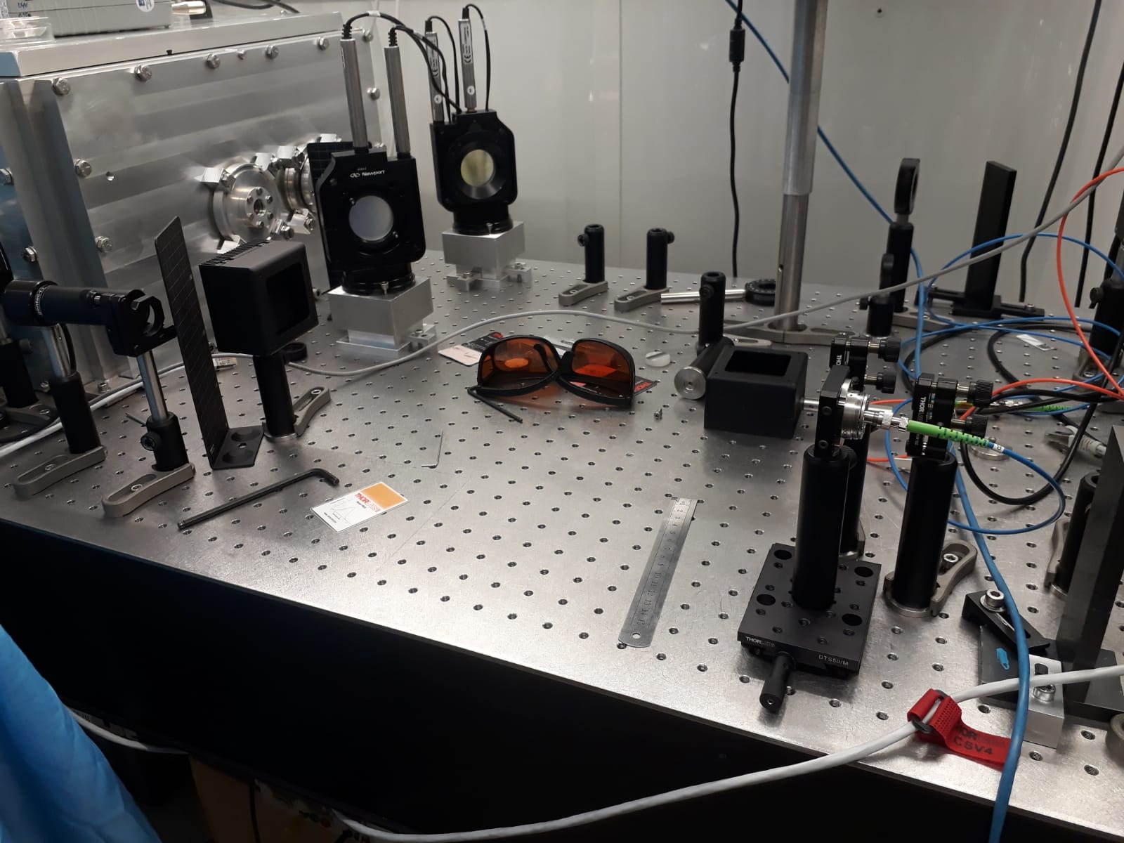
- The setup for T test was moved outside the metal box with the same distances between the injection beam and mirror ~ 50 cm. and the distance between the injection laser and the mirror next to it ~ 9 cm.
-
- Observation for T is done at full angle and at half angle of reflection ( the mirror was tilted to achive this )
-
- we observed that after each change in the distance from the center the power meter needed to be aligned to have the max power.
- after doing all the measurements for the range from the center we made it again for the center only and the consistance of the transmission was good.
The file stating the measurements is : Test Cavity _ Mirrors transmission _ outside box
note: the laser used for the test is the Koheras
details on the pwer used, mirrors, power meter, filters, ....etc are shown in the Excel data sheets
Done By : Loic , Manar and Ahmed |
| Attachment 1: Test_Cavity___Mirrors_transmission___Inside_box.xlsx
|
| Attachment 2: Test_Cavity___Mirrors_transmission___outside_box.xlsx
|
| Attachment 3: set_up_for_transmission_measurement_outside_box.jpeg
|
 |
| Attachment 4: setup_fot_T_measurement_Injection_laser_and_mirrors_reflected_on_at_angle_and_half_angle.jpeg
|
 |
| Attachment 5: Mirrors_Tested.jpeg
|
 |
| Attachment 6: set_up_for_mirror_and_power_meter.jpeg
|
 |
|
62
|
Tue Jan 12 10:44:57 2021 |
Ronic Chiche | Fixed | issue | lasers and optics | Optical room | Origami SN2440 133MHz laser power measurment... and failure |
we received from NKT the Origami SN2440 133MHz oscillator from repair on 2020/12/17
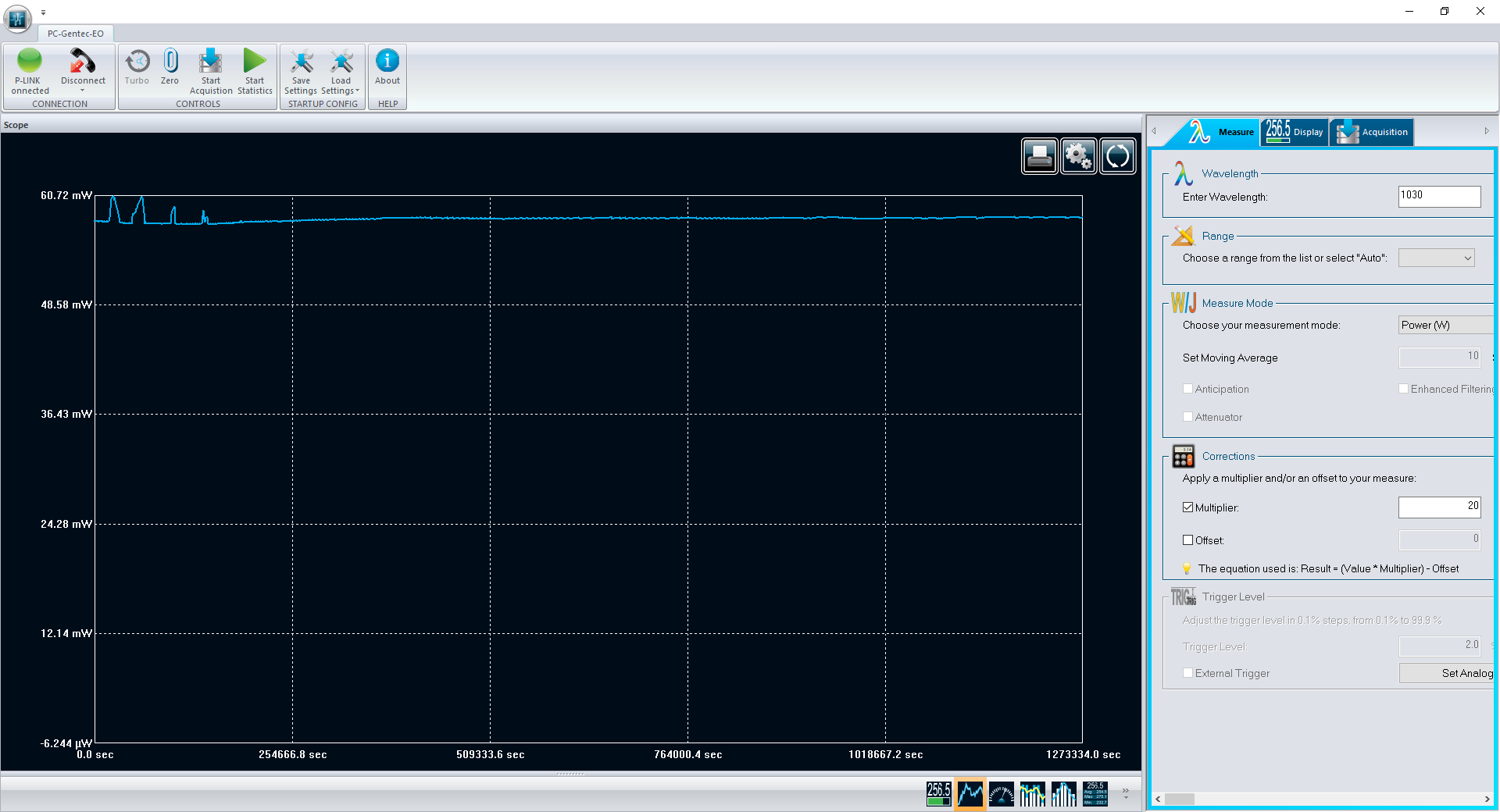
and we measured the power trend from 2020/12/21 until the whole winter Hollyday, during 14 days and 17h (1 273 334 s).
the power was quite constant, about 58mW (the measurement has been done with the OD2 filter and using a (x20) factor in the software to compensate for it),
except for some peaks at the beginning of the measurement to 60.7mW.
I tried to reproduce these peaks by switching on several lights in the room and the airflow ceil but the effect is neglectable,
thus these peaks seem to really come from the oscillator power.
at the beginning of January, the oscillator suffered a back reflection from the rugged anodized convex surface of the power meter (apparently not from the OD2 filter itself) and the laser stopped immediately to modelock.
the laser power dropped to 0 and the laser controller led started to blink red. NKT has been contacted and they think it could be the laser pump diodes that have been damaged.
for the future, we will have to install a fixed optical isolator from the start, even for short operations.
|
| Attachment 1: 133mhzpower.PNG
|
 |
| Attachment 2: 133mhz_power_zoom.png
|
 |
|
63
|
Thu Jun 10 17:55:15 2021 |
Ronic Chiche | Fixed | info | lasers and optics | Optical room | Origami SN2440 133MHz laser tests |
Today, we received the Origami SN2440 133MHz oscillator from repair (NKT mentioned a defective wire inside the controller....)
We immediately installed it behind an isolator (Faraday rotator+PBS+halfwave plate).
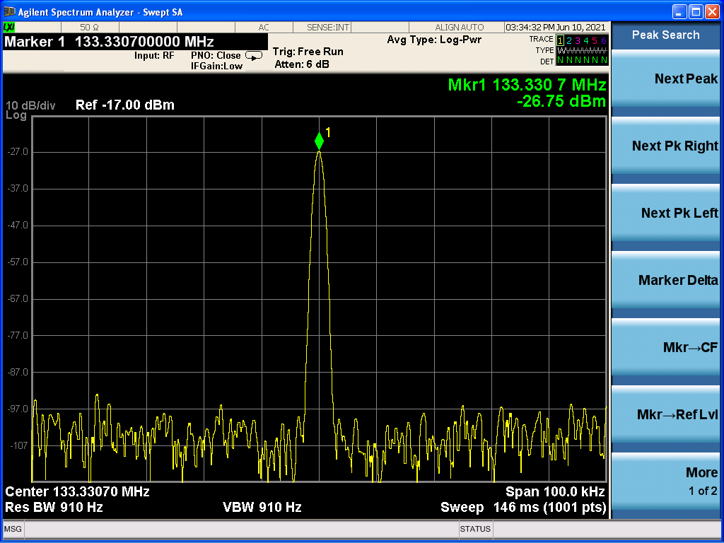
the output power is around 60mW.
the spectrum is around 1030nm
the repetition rate is around 133.33MHz |
| Attachment 1: IMG_20210610_161502.jpg
|
 |
| Attachment 2: spectre_133MHz.PNG
|
 |
| Attachment 3: Screen_0015.png
|
 |
|
64
|
Mon Jul 5 14:14:01 2021 |
Manar Amer | Fixed | report | lasers and optics | detectors and electronics | Optical room | OEwaves CW Laser - Phase Noise |
- We started measuring the phase noise on the OEwaves CW laser.
- Class 3b
- wavelength 1.5 um
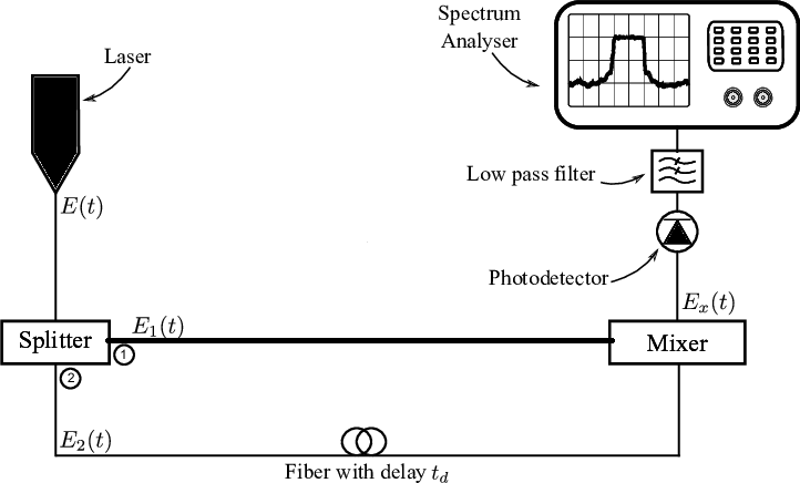
- The procedure is done using self coupling of the laser
- splitter 50%-50%\
- delay line 100 m
- all fibers are PM type (polarity maintained)
- Photodetector is "lab buddy", very fast diode.
- Note: différance from schematic (we did not use a low pass filter)
|
| Attachment 1: 20210207_OEwaves_laser.jpg
|
 |
| Attachment 2: 20210207_Self_coupling_setup.jpg
|
 |
| Attachment 3: Schematic-setup-for-optical-delayed-self-coupling-detection.png
|
 |
|
65
|
Mon Jul 5 14:40:57 2021 |
Manar Amer | Fixed | report | lasers and optics | detectors and electronics | Optical room | OEwaves CW Laser - Phase Noise |
a correction on the wavelength of the laser it is 1030 um
| Manar Amer wrote: |
- We started measuring the phase noise on the OEwaves CW laser.
- Class 3b
- wavelength 1.5 um
- The procedure is done using self coupling of the laser
- splitter 50%-50%\
- delay line 100 m
- all fibers are PM type (polarity maintained)
- Photodetector is "lab buddy", very fast diode.
- Note: différance from schematic (we did not use a low pass filter)
|
|
|
66
|
Mon Jul 5 14:46:44 2021 |
Manar Amer | Fixed | report | lasers and optics | detectors and electronics | Optical room | OEwaves CW Laser - Phase Noise |
correction on unit 1030 nm
| Manar Amer wrote: |
|
a correction on the wavelength of the laser it is 1030 um
| Manar Amer wrote: |
- We started measuring the phase noise on the OEwaves CW laser.
- Class 3b
- wavelength 1.5 um
- The procedure is done using self coupling of the laser
- splitter 50%-50%\
- delay line 100 m
- all fibers are PM type (polarity maintained)
- Photodetector is "lab buddy", very fast diode.
- Note: différance from schematic (we did not use a low pass filter)
|
|
|
|
67
|
Wed Mar 23 18:11:22 2022 |
Manar Amer | Fixed | report | utilities | Optical room | Dust Cleaning of SBox |
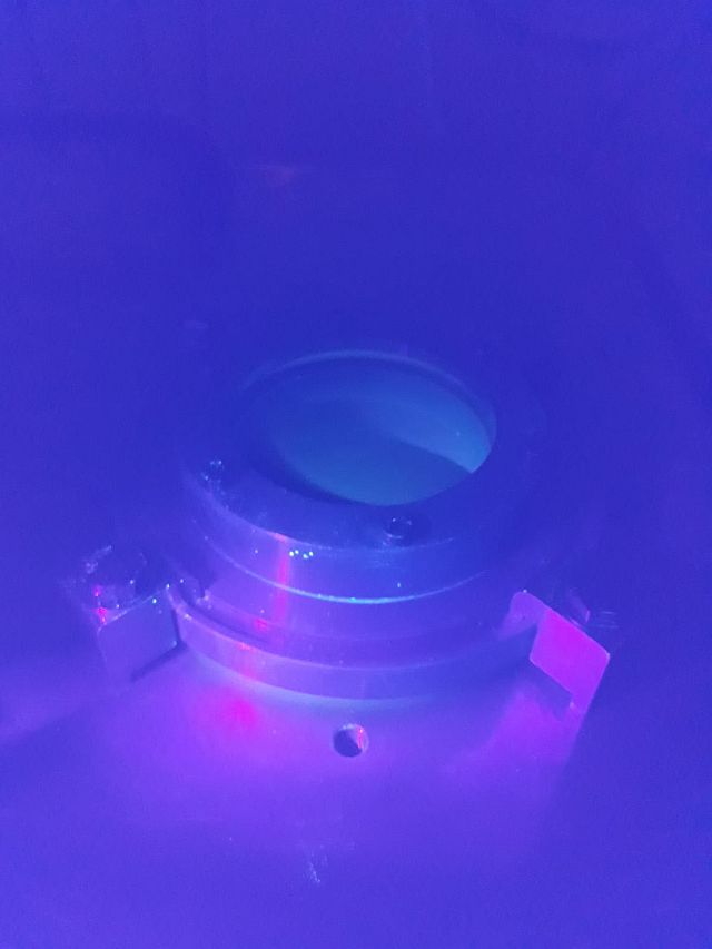
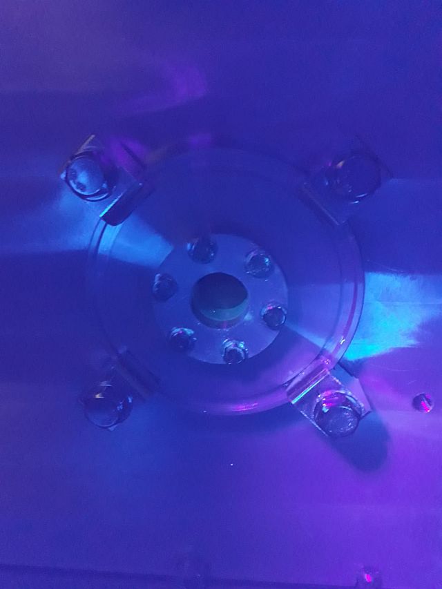
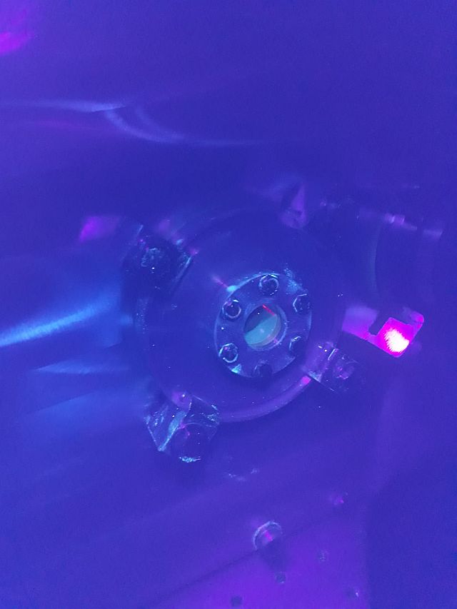
An Initial cleaning of the KBoX outside was done, All the optics and mechanics placed that were on the table were removed.
Only the old Mitylaser amplifier remains on the table.
Since we will be using the ThomX Celia amplifier, we will remove it and place it in a secure location (to be decided).
Tomorrow a cleaning of the inside of the cavity box is to be done. |
| Attachment 1: Log_Top_window.jpg
|
 |
| Attachment 2: Log_Reflection_window.jpg
|
 |
| Attachment 3: Log_Injection_Side_window.jpg
|
 |
| Attachment 4: Log_Injection_side_window2.jpg
|
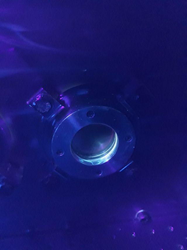 |
|
68
|
Wed Mar 23 18:17:45 2022 |
Manar Amer | Fixed | report | utilities | Optical room | Dust Cleaning of SBox |
The cleaning was done twice with half an hour interval between the two times
reading on the dust meter was taken after each time, and it was zero averaged over a 10-min
| Manar Amer wrote: |
|
An Initial cleaning of the KBoX outside was done, All the optics and mechanics placed that were on the table were removed.
Only the old Mitylaser amplifier remains on the table.
Since we will be using the ThomX Celia amplifier, we will remove it and place it in a secure location (to be decided).
Tomorrow a cleaning of the inside of the cavity box is to be done.
|
|
|
69
|
Tue Mar 29 16:23:00 2022 |
Manar Amer | Fixed | report | lasers and optics | cabling | Optical room | Mightylaser Amplifier |
Migthylaser amplifier has been moved from the SBox table to the PLIC table.
|
|
70
|
Tue Mar 29 16:27:34 2022 |
Manar Amer | Fixed | report | utilities | Optical room | Spincoater - Mirrror cleaning |
In preparation for cleaning the mirrors.
The spincoater has been moved with its bump into the sas of the SBox.
The pure water used will be provided by Alice, as the previous source in the workshop is not available.
|
|
71
|
Wed Mar 30 18:53:01 2022 |
Manar Amer | Fixed | report | mechanics | lasers and optics | utilities | Optical room | Dust Cleaning of SBox |
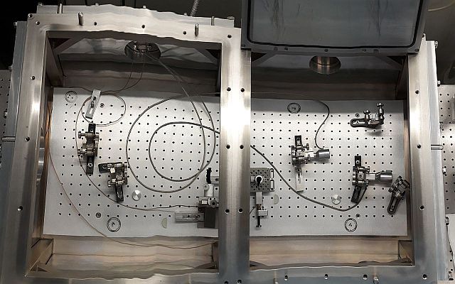
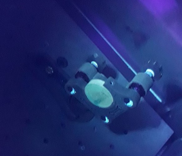
The inside of the cavity was cleaned today. It was very dirty and had big dust particles and fibers inside.
Cleaning was done for everything; wall, floor, fixed mounts, wires (still have some dust difficult to remove), edges.
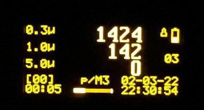
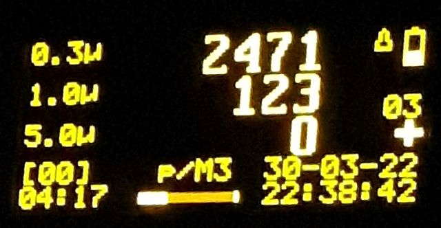
The dust meter average was measured outside the cavity (2471 p/m3 av 6 min) and inside after cleaning (1424 p/m3 av 10 min).
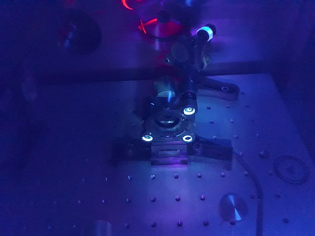
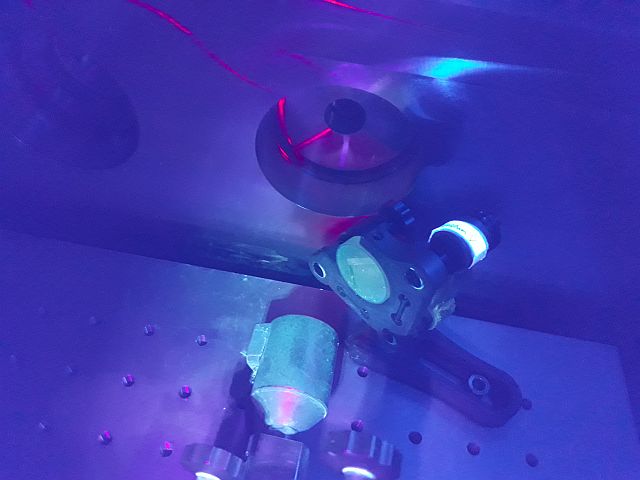
The cavity was left open under the clean air flow, will observe it under UV, clean and measure Dust tomorrow.
Images attached are after cleaning.
Objects inside the cavity at the moment :
- 4 main mirror mounts
- 4 mirror fixers on mounts and 3 screws each (total 12)
- 2 reflecting mirror mounts
- 2 dielectric mirrors (mounted and to be cleaned)
- two mounts for D-shaped mirrors.
- 2 D-shaped mirrors (unmounted, and they will need cleaning)
- 2 metal irises (pinholes)
| Manar Amer wrote: |
|
The cleaning was done twice with half an hour interval between the two times
reading on the dust meter was taken after each time, and it was zero averaged over a 10-min
| Manar Amer wrote: |
|
An Initial cleaning of the KBoX outside was done, All the optics and mechanics placed that were on the table were removed.
Only the old Mitylaser amplifier remains on the table.
Since we will be using the ThomX Celia amplifier, we will remove it and place it in a secure location (to be decided).
Tomorrow a cleaning of the inside of the cavity box is to be done.
|
|
|
| Attachment 1: 20220330_SBox_Inside_Cavity_Box.jpg
|
 |
| Attachment 2: 20220330_Injection_Mount_UV.jpg
|
 |
| Attachment 3: 20220330_Reflection_One_UV.jpg
|
 |
| Attachment 4: 20220330_Reflection_two_UV.jpg
|
 |
| Attachment 5: 20220330_Dust_Meter_Inside_cavity_Av10min.jpg
|
 |
| Attachment 6: 20220330_Dust_Meter_Outside_cavity_Av6min.jpg
|
 |
|
72
|
Thu Mar 31 13:29:01 2022 |
Manar Amer | Fixed | report | mechanics | lasers and optics | utilities | Optical room | Dust Cleaning of SBox |
After an overnight where the cavity box was left open, a measurement of the Dust meter was taken:
Outside on the optical table on direct air flux (1701 p/m3 Av 10 min) and
Inside the cavity box (998 p/m3 Av 10 min)
The dust inside the cavity has decreased by ~ 30 % for 0.3 u particles.
Note: the cavity box is still open.
| Manar Amer wrote: |
|
The inside of the cavity was cleaned today. It was very dirty and had big dust particles and fibers inside.
Cleaning was done for everything; wall, floor, fixed mounts, wires (still have some dust difficult to remove), edges.
The dust meter average was measured outside the cavity (2471 p/m3 av 6 min) and inside after cleaning (1424 p/m3 av 10 min).
The cavity was left open under the clean air flow, will observe it under UV, clean and measure Dust tomorrow.
Images attached are after cleaning.
Objects inside the cavity at the moment :
- 4 main mirror mounts
- 4 mirror fixers on mounts and 3 screws each (total 12)
- 2 reflecting mirror mounts
- 2 dielectric mirrors (mounted and to be cleaned)
- two mounts for D-shaped mirrors.
- 2 D-shaped mirrors (unmounted, and they will need cleaning)
- 2 metal irises (pinholes)
| Manar Amer wrote: |
|
The cleaning was done twice with half an hour interval between the two times
reading on the dust meter was taken after each time, and it was zero averaged over a 10-min
| Manar Amer wrote: |
|
An Initial cleaning of the KBoX outside was done, All the optics and mechanics placed that were on the table were removed.
Only the old Mitylaser amplifier remains on the table.
Since we will be using the ThomX Celia amplifier, we will remove it and place it in a secure location (to be decided).
Tomorrow a cleaning of the inside of the cavity box is to be done.
|
|
|
|
| Attachment 1: 20220331_Dust_Meter_Outside_cavity_Av10min.jpg
|
 |
| Attachment 2: 20220331_Dust_Meter_Inside_cavity_Av10min.jpg
|
 |
|
73
|
Mon Apr 4 13:58:23 2022 |
Manar Amer | Fixed | issue | detectors and electronics | utilities | Optical room | Clean Airflow Dust measurements |
The dust meter cap was cleaned using Alcohol, and using the filter white cap the dust count was (0 Av. 10 min)
After the dust counter was hand held in direct airflow, it counted (1581 p/m3 Av. 2 min).
I tested the count also in the SAS, and it counted twice the amount ~ 4500 p/m3
Note: discussion on the next steps to take for the airflow filtering !!!!!!!! |
|
74
|
Fri Apr 8 19:27:12 2022 |
Manar Amer | Fixed | issue | detectors and electronics | utilities | Optical room | Clean Airflow Dust measurements |
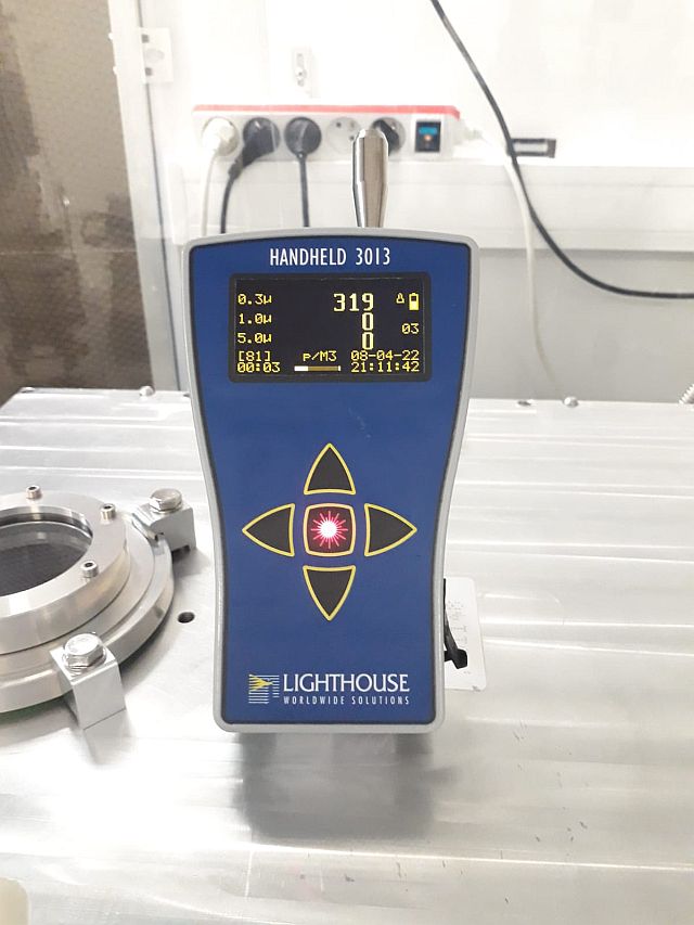
Dust measurement done today on top of the SBox average 10min
| Manar Amer wrote: |
|
The dust meter cap was cleaned using Alcohol, and using the filter white cap the dust count was (0 Av. 10 min)
After the dust counter was hand held in direct airflow, it counted (1581 p/m3 Av. 2 min).
I tested the count also in the SAS, and it counted twice the amount ~ 4500 p/m3
Note: discussion on the next steps to take for the airflow filtering !!!!!!!!
|
|
| Attachment 1: 20220408_DustMeasurement.jpg
|
 |
|
75
|
Wed Apr 13 18:42:50 2022 |
Manar Amer | Fixed | report | lasers and optics | utilities | Optical room | Spincoater - Mirrror cleaning |
Used the spincoater and pure water to clean dielectric mirrors which will be installed inside the SBox for directing the reflection line.
The method : place pure alchole on mirror - wipe it using white sterile tissue (in one direction) - clean with pure water in spincoater suing cotton swap .
After multible rounds, the result in the images was obtained. there is still a significant amount of dust particles (not all could be dust!!).
Not sure if the reason is the cleaning method ?? will invistegate it more !!!
| Manar Amer wrote: |
|
In preparation for cleaning the mirrors.
The spincoater has been moved with its bump into the sas of the SBox.
The pure water used will be provided by Alice, as the previous source in the workshop is not available.
|
|
| Attachment 1: Reflection_one_front_after_cleaning.jpg
|
 |
| Attachment 2: reflection_two_front_before_cleaning.jpg
|
 |
| Attachment 3: Reflection_two_front_after_cleaning.jpg
|
 |
|
76
|
Wed Apr 20 19:05:37 2022 |
Manar Amer | Fixed | report | lasers and optics | Optical room | KBox Alignment |
Starting with the alignment of the KBox using CW Koheras.
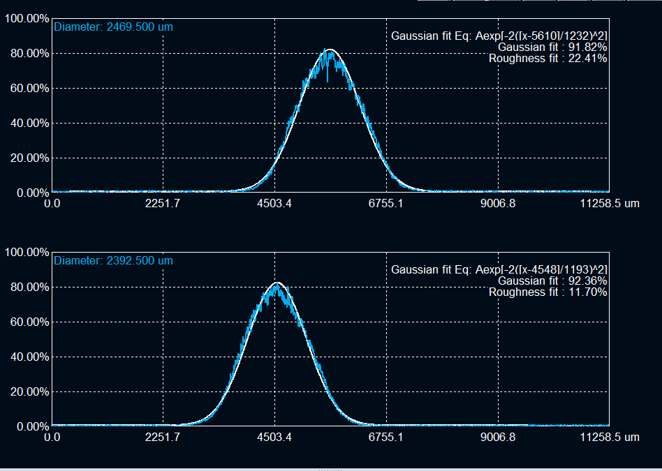
The size of the CW output from the collimator at 1 meter from is ~ 2.4 mm, to be adjusted with lenses to match the cavity !!! (attached image)
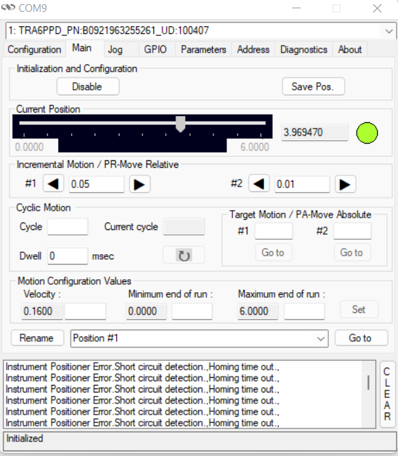
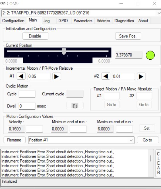
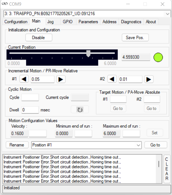
For the 2 alignment mirrors, I am only able to control 3 axes for now (motor issue for the fourth to be fixed !!) , Horizontal and vertical for Ma1 and Horizontal for Ma2(closes to injection window).
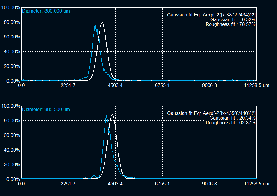
Started with only irises placed on both the M1 and M2. Placed a beam profiler at the window behind M2 to observe an output beam.
Motors position for the 3 axes and beam shape and position after M2 attached. |
| Attachment 1: CW_Koheras_1meter_ColimatorOutput_NE40A_NE10B_NE01A_Beam.bmp
|
| Attachment 2: CW_Koheras_1meter_ColimatorOutput_NE40A_NE10B_NE01A_BeamFit.png
|
 |
| Attachment 3: Ma1_Horizontal_Position.png
|
 |
| Attachment 4: Ma1_Vertical_Position.png
|
 |
| Attachment 5: Ma2_Horizontal_Position.png
|
 |
| Attachment 6: Transmission_M2_Irises_No_Mirrors_Beam.jpg
|
 |
| Attachment 7: Transmission_M2_Irises_No_Mirrors_BeamFit.png
|
 |
|
77
|
Mon Apr 25 17:28:29 2022 |
Manar Amer | Fixed | report | lasers and optics | Optical room | SBox Alignment |
SBox alignment, using CW laser Koheras power 1 mW
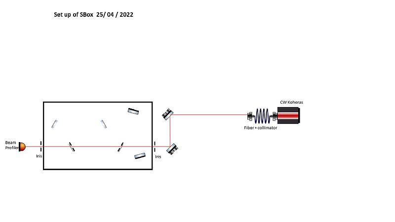
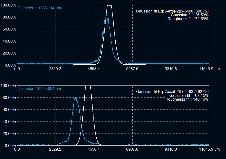
- Finished M1 and M2 alignment using the diffraction patterns seen on the beam profiler, the beam fit is not very good ?? (image taken)
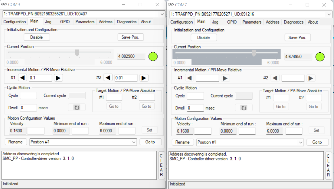
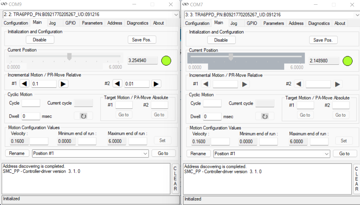
- Positions of Ma1 and Ma2 motors are registered (image taken)
- Placed Fixed 2 irises at M1 window and M2 window (Image taken while both are closed)
- Distance between the collimator and beam profiler ~ 2 m
- Distance between collimator and M1 diaphragm ~ 1 m
- Distance between collimator and M2 diaphragm ~ 1.6 m
| Manar Amer wrote: |
|
Starting with the alignment of the KBox using CW Koheras.
The size of the CW output from the collimator at 1 meter from is ~ 2.4 mm, to be adjusted with lenses to match the cavity !!! (attached image)
For the 2 alignment mirrors, I am only able to control 3 axes for now (motor issue for the fourth to be fixed !!) , Horizontal and vertical for Ma1 and Horizontal for Ma2(closes to injection window).
Started with only irises placed on both the M1 and M2. Placed a beam profiler at the window behind M2 to observe an output beam.
Motors position for the 3 axes and beam shape and position after M2 attached.
|
|
| Attachment 1: SBox_Setup.jpg
|
 |
| Attachment 2: Ma1_Ma2_Horizontal_Position.png
|
 |
| Attachment 3: Ma1_Ma2_Vertical_Position.png
|
 |
| Attachment 4: Output_afterM2_Diaghragm_On_M1_M2_Beam.jpg
|
 |
| Attachment 5: Output_afterM2_Diaghragm_On_M1_M2_BeamFit.png
|
 |
| Attachment 6: Output_afterM2_Diaghragm_On_M1_M2_Beam_Outside_Irises_Installed_and_Closed.jpg
|
 |
|
78
|
Mon Apr 25 17:58:01 2022 |
Manar Amer | Fixed | report | lasers and optics | Optical room | SBox Alignment |
After pointers and Advice from Aurélien,
improvement of the beam alignment through M1 and M2 irises was done.
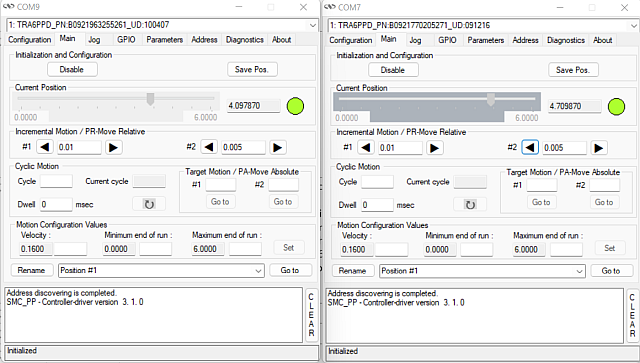
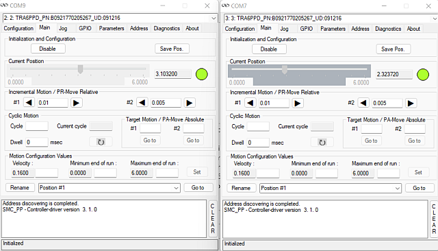
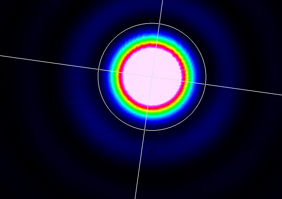
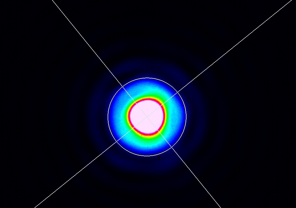
To improve the image on the beam profiler, I cleaned the alignment mirrors and the windows using pure ethanol and optical lens cleaning tissue,
a significant improvement after cleaning the inside of M2 Window. Images have less dust diffraction rings.
Attached new images of the beam:
- New Ma1 and Ma2 motor position
- After M1 pinhole optimized (saturated)
- After M2 and M1 pinhole optimizing (saturated and not)
| Manar Amer wrote: |
|
SBox alignment, using CW laser Koheras power 1 mW
- Finished M1 and M2 alignment using the diffraction patterns seen on the beam profiler, the beam fit is not very good ?? (image taken)
- Positions of Ma1 and Ma2 motors are registered (image taken)
- Placed Fixed 2 irises at M1 window and M2 window (Image taken while both are closed)
- Distance between the collimator and beam profiler ~ 2 m
- Distance between collimator and M1 diaphragm ~ 1 m
- Distance between collimator and M2 diaphragm ~ 1.6 m
| Manar Amer wrote: |
|
Starting with the alignment of the KBox using CW Koheras.
The size of the CW output from the collimator at 1 meter from is ~ 2.4 mm, to be adjusted with lenses to match the cavity !!! (attached image)
For the 2 alignment mirrors, I am only able to control 3 axes for now (motor issue for the fourth to be fixed !!) , Horizontal and vertical for Ma1 and Horizontal for Ma2(closes to injection window).
Started with only irises placed on both the M1 and M2. Placed a beam profiler at the window behind M2 to observe an output beam.
Motors position for the 3 axes and beam shape and position after M2 attached.
|
|
|
| Attachment 1: Ma1_Ma2_Horizontal_Position_Optimized.png
|
 |
| Attachment 2: Ma1_Ma2_Vertical_Position_Optimized.png
|
 |
| Attachment 3: After_M1_diaphram_1m_Saturated_Beam_Optimized.jpg
|
 |
| Attachment 4: After_M2_M1_diaphram_Saturated_Beam_Optimized.jpg
|
 |
| Attachment 5: After_M2_M1_diaphram_Beam_Optimized.jpg
|
 |