| ID |
Date |
Author |
Status |
Type |
Category |
Location |
Title |
|
232
|
Tue Mar 4 18:51:57 2025 |
Ronic Chiche | Under Process | info | mechanics | lasers and optics | Optical room | Alignment of a 2-mirror FP cavity |
today with Alice,
- we measured the height of the SBOX windows center : 140mm from the optical table.
- we set the laser fiber colimator exactly at this height.
- we placed 2 mirrors to align the future telescope path at exactly 140mm height along the whole possible travel of the lenses in order to keep them aligned.
the horizontal position is also aligned on this path and a ruler has been placed along this path to help to move the future telescope lenses without misalignment.
- we aligned 2 iris on this path to keep this path axis in case of misalignment.
- we placed 2 iris at the center of the input and output FP-cavity windows.
- we precisely aligned the laser beam on these iris.
in the next days, we need to align the mounts in the SBOX and align also the 2 FP-cavity mirrors.
the output mirror will be a "bad" ThomX 2.24m ROC ULE mirror and the input mirror will be a plan 460ppm Gamma Factory mirror. |
|
231
|
Tue Mar 4 18:33:26 2025 |
Ronic Chiche | Fixed | info | utilities | Optical room | optical table cleaning |
now, it seems the table is clean enough (dust meter counts 0 particles) to install a 2 mirrors FP-cavity.
| Ronic Chiche wrote: |
|
this afternoon, we checked the dust meter which is at 0 for 1 and 5µm dust particles but ~ 2000-3000 for 0.3µm particles.
we opened the two top panels to let the air flow clean the inside of the vessel.
we observed some other minor oxydised regions (than the one taken in picture) on the external parts of the inox panels but at first sight, nothing inside the vessel.
| Ronic Chiche wrote: |
|
this morning with Alice and Daniele, we removed all the optics elements and equipments from the SBOX optical table and started to clean it.
the dust meter count 0 on all particle sizes after the cleaning.
we observed a small part of the SBOX which seems to be oxydised (see picture).
the two previously used mirrors of the SBOX (C23018/7 and C23017/2) were already in their plastic boxes outside of the SBOX.
they are still on the optical table.
we have to decide which mirrors to put in the cavity:
if we don't want to use a "new" ThomX coupling mirror M1, we have to use a Gamma-factory mirror (161185) with T=460ppm for example (we don't have any other FS plan mirrors).
if we don't plan to work at high power in the SBOX for the moment, we could use an "old" ThomX M2 mirror with ROC=2.241m (C1611/11) to avoid any risk of contamination of a "new" ThomX M2 mirror.
|
|
|
|
230
|
Mon Dec 16 10:20:56 2024 |
Ronic Chiche | Under Process | issue | lasers and optics | Optical room | CELIA 100W laser amplifier repair |
friday morning, we add a zoom call with Jerome Lhermite about the amplifier repair.
he approximately confirmed the amplifier scheme from the Loic thesis.
he suggested to:
1) identify the circulator ports.
they have some tapes with text written on them.
the goal is to understand if it is still used in the present setup and if a CFBG could still be connected to it (and from which one end could be the fiber seen "broken").
2) use the 5% output tap of the amplifier to check if some light is outed if the input or circulator fibers are injected with 1st stage switched ON or OFF.
3) follow the "broken" fiber to check to which element it is connected to => we should need to unroll the fibers in the bottom "fiber cassette"... :-(
| Ronic Chiche wrote: |
|
this afternoon, we saw some electric cables badly connected to their power supply.
we fixed it by soldering them together and screwing the result to the power supply.
(see 1st image)
we lift the plate of the 1st stage and we check for optical leakage in the fibers (see 2nd image + picture of the top part of the cassette).
(Aurélien took several images)
without the 1st stage amplification, we saw some lealage only in the bottom part of the "optical cassette".
light was scattered mostly from one side (2 spots) and we saw also very weak scattering in the other directions.
with the 1st stage amplification, we clearly saw the losses from the bent fibers inside the top part of the cassette => it's a good sign.
but after the 5%-10% coupler (the one used for the diagnostic of the power to allow the use of the 2nd stage), we don't see any losses, which means there is no light in this part !
the fiber break could be in between...
Aurélien should send the images to Jérome to get a diagnostic.
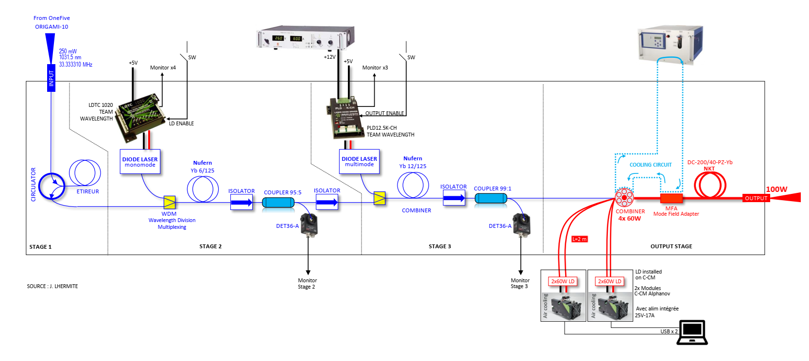
the old schematic is attached but it has been modified in the Loic Thesis (p. 165)
we identified the black optics components as 2 isolators (AFW-PISO-30-1W-FB) and 1 circulator (AFW-CIR-PM-30) from AFW technologies.
| Ronic Chiche wrote: |
|
this morning with Alice, we sent the Menhir 160MHz injected in a fiber (with 6mW at the end of a long fiber) into the laser amplifier, to look for leakage or damage in the first stages of the amplifier (the amplifier is totally off).
first of all, we checked for light scattering around the laser crate with a sensitive optical card => nothing
and then, we checked for light scattering inside the laser crate with an optical viewer => we just saw 1 or 2 small spots located at the end of an optical element at the 2nd stage level.
but it's difficult to understand the optical path and know the different elements with the 1st stage still in place.
we think it is mandatory to open the top of the crate and lift the 1st stage to have a better look inside the optical parts which are at the 2nd and 3rd stage levels:
we could remove the front side of the crate without any damage to any fibers in the crate.
we just saw 1 fiber, glued to an optical element on the 2nd stage, and going to the 3rd stage.
the 1st stage is just an electronics parts stage which seems easy to be removed.
... to be discussed...
|
|
|
| Attachment 1: Sans_titre.png
|
 |
|
229
|
Fri Dec 6 16:59:57 2024 |
Ronic Chiche | Fixed | info | utilities | Optical room | optical table cleaning |
this afternoon, we checked the dust meter which is at 0 for 1 and 5µm dust particles but ~ 2000-3000 for 0.3µm particles.
we opened the two top panels to let the air flow clean the inside of the vessel.
we observed some other minor oxydised regions (than the one taken in picture) on the external parts of the inox panels but at first sight, nothing inside the vessel.
| Ronic Chiche wrote: |
|
this morning with Alice and Daniele, we removed all the optics elements and equipments from the SBOX optical table and started to clean it.
the dust meter count 0 on all particle sizes after the cleaning.
we observed a small part of the SBOX which seems to be oxydised (see picture).
the two previously used mirrors of the SBOX (C23018/7 and C23017/2) were already in their plastic boxes outside of the SBOX.
they are still on the optical table.
we have to decide which mirrors to put in the cavity:
if we don't want to use a "new" ThomX coupling mirror M1, we have to use a Gamma-factory mirror (161185) with T=460ppm for example (we don't have any other FS plan mirrors).
if we don't plan to work at high power in the SBOX for the moment, we could use an "old" ThomX M2 mirror with ROC=2.241m (C1611/11) to avoid any risk of contamination of a "new" ThomX M2 mirror.
|
|
|
228
|
Tue Dec 3 13:51:52 2024 |
Ronic Chiche | Fixed | info | utilities | Optical room | optical table cleaning |
this morning with Alice and Daniele, we removed all the optics elements and equipments from the SBOX optical table and started to clean it.
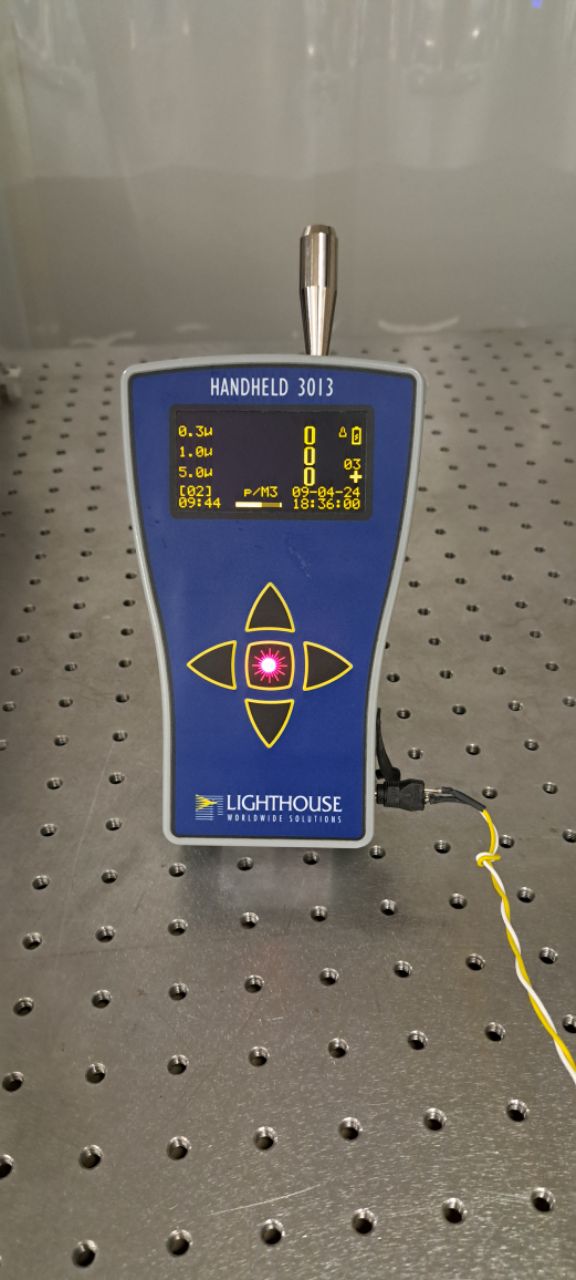
the dust meter count 0 on all particle sizes after the cleaning.
we observed a small part of the SBOX which seems to be oxydised (see picture).
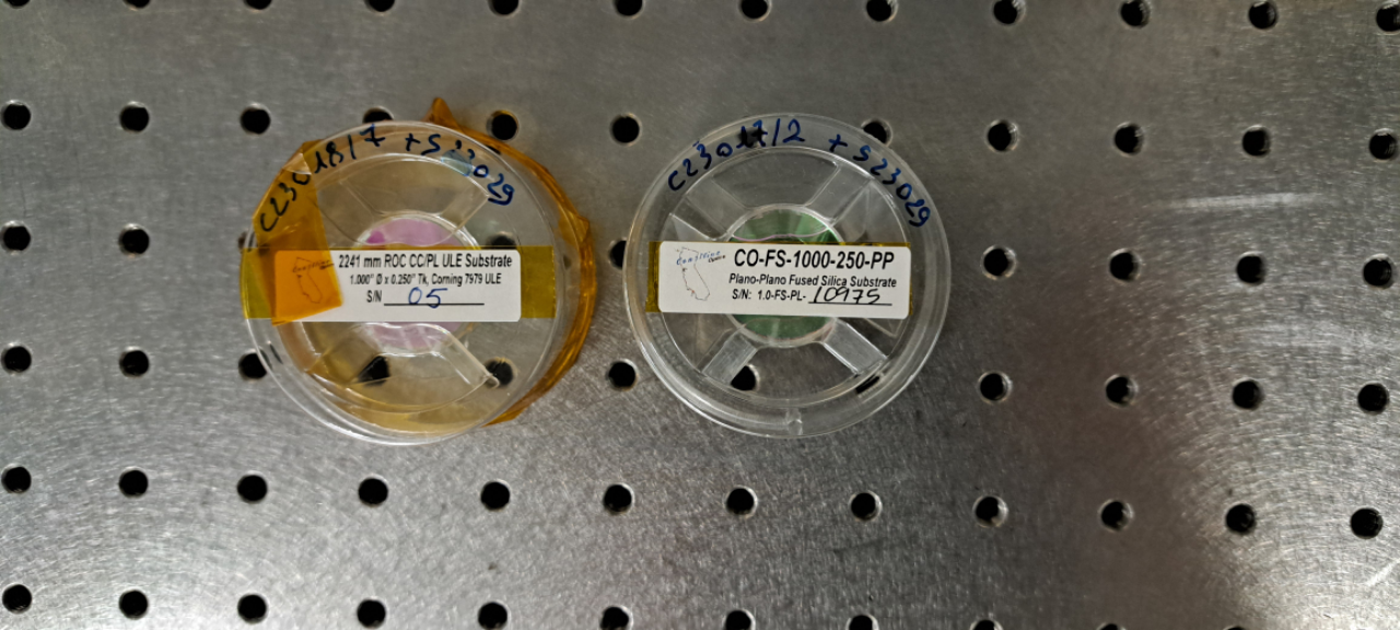
the two previously used mirrors of the SBOX (C23018/7 and C23017/2) were already in their plastic boxes outside of the SBOX.
they are still on the optical table.
we have to decide which mirrors to put in the cavity:
if we don't want to use a "new" ThomX coupling mirror M1, we have to use a Gamma-factory mirror (161185) with T=460ppm for example (we don't have any other FS plan mirrors).
if we don't plan to work at high power in the SBOX for the moment, we could use an "old" ThomX M2 mirror with ROC=2.241m (C1611/11) to avoid any risk of contamination of a "new" ThomX M2 mirror. |
| Attachment 1: Oxydation.jpg
|
 |
| Attachment 2: 20241203_113105.jpg
|
 |
| Attachment 3: 20241203_125359.jpg
|
 |
|
227
|
Fri Nov 29 16:50:04 2024 |
Alice Renaux | Under Process | info | lasers and optics | Optical room | Menhir 216MHz laser |
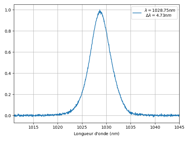
The Menhir 216MHz laser has been put back in place on the cavity table. Its output power is measured to be 160mW with an attenuator. Its spectrum is available in "spectre.xlsx" and "spectre.png". The main wavelength is a bit shorter (1028.75nm) and the spectrum a bit narrower (4.73nm) than expected.
|
| Attachment 1: spectre.xlsx
|
| Attachment 2: spectre.png
|
 |
|
226
|
Fri Nov 29 12:06:05 2024 |
Alice Renaux | Fixed | info | lasers and optics | Optical room | Menhir 160MHz laser |
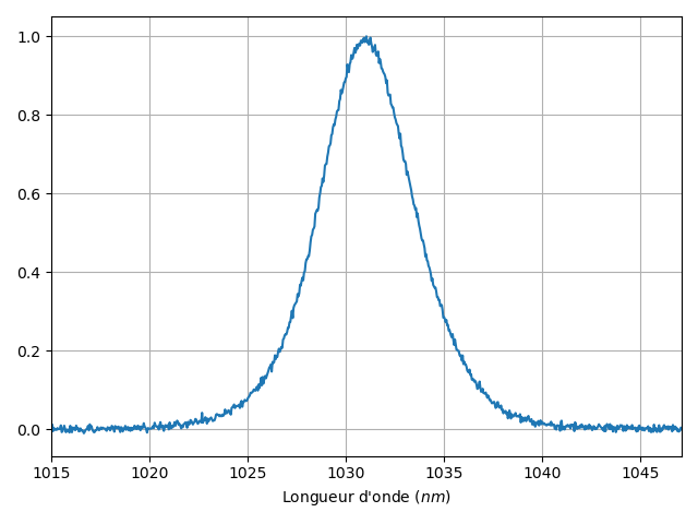
The Menhir 160MHz has been put back in place on the CELIA amplifier setup. Its output power is measured to be 150-160mW with an attenuator as expected. Its spectrum is available in "spectre_avant_cvbg.xlsx" and "spectre_avant_cvbg.png".
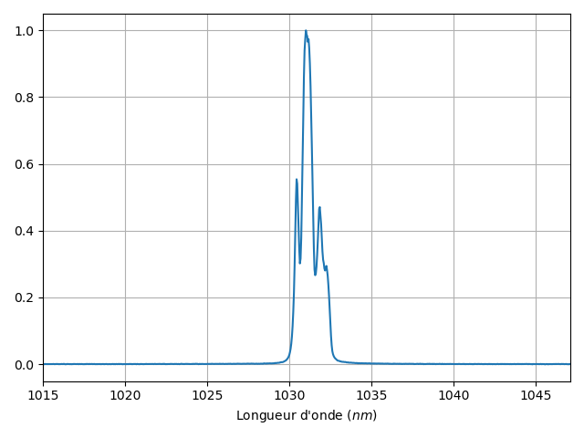
The pulses are stretched by means of a CVBG. Their spectrum is available in "spectre_apres_cvbg.xlsx" and "spectre_apres_cvbg.png".
The laser is coupled into an optical fiber with an output power of 11.5mW for a 32mW input.
|
| Attachment 1: spectre_avant_cvbg.xlsx
|
| Attachment 2: spectre_apres_cvbg.xlsx
|
| Attachment 3: spectre_avant_cvbg.png
|
 |
| Attachment 4: spectre_apres_cvbg.png
|
 |
|
225
|
Wed Oct 2 18:12:54 2024 |
Ronic Chiche | Under Process | issue | lasers and optics | Optical room | CELIA 100W laser amplifier repair |
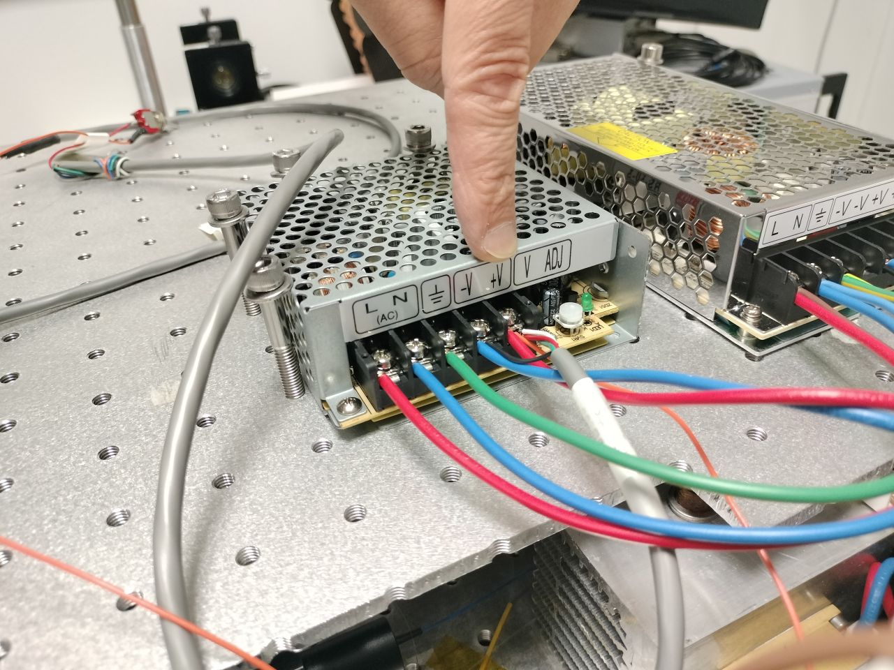
this afternoon, we saw some electric cables badly connected to their power supply.
we fixed it by soldering them together and screwing the result to the power supply.
(see 1st image)
we lift the plate of the 1st stage and we check for optical leakage in the fibers (see 2nd image + picture of the top part of the cassette).
(Aurélien took several images)
without the 1st stage amplification, we saw some lealage only in the bottom part of the "optical cassette".
light was scattered mostly from one side (2 spots) and we saw also very weak scattering in the other directions.
with the 1st stage amplification, we clearly saw the losses from the bent fibers inside the top part of the cassette => it's a good sign.
but after the 5%-10% coupler (the one used for the diagnostic of the power to allow the use of the 2nd stage), we don't see any losses, which means there is no light in this part !
the fiber break could be in between...
Aurélien should send the images to Jérome to get a diagnostic.
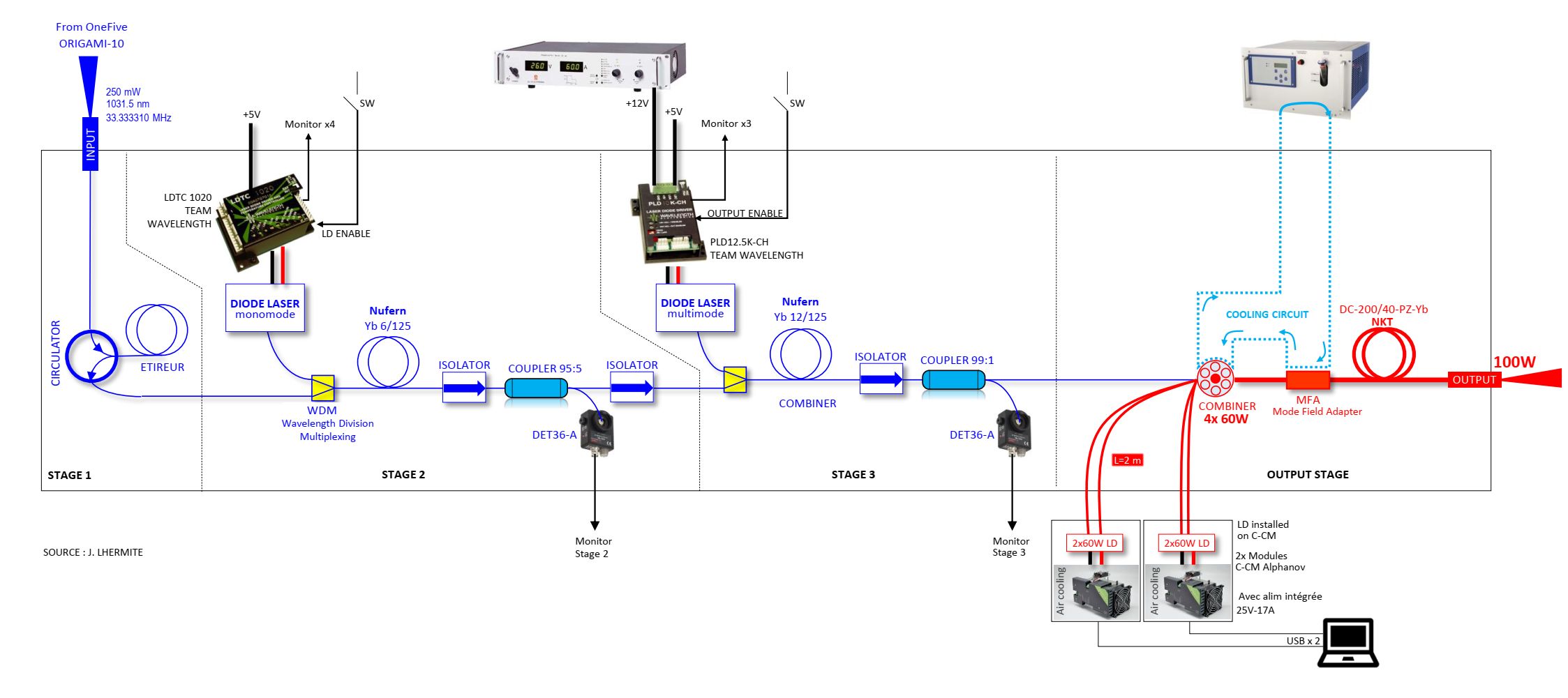
the old schematic is attached but it has been modified in the Loic Thesis (p. 165)
we identified the black optics components as 2 isolators (AFW-PISO-30-1W-FB) and 1 circulator (AFW-CIR-PM-30) from AFW technologies.
| Ronic Chiche wrote: |
|
this morning with Alice, we sent the Menhir 160MHz injected in a fiber (with 6mW at the end of a long fiber) into the laser amplifier, to look for leakage or damage in the first stages of the amplifier (the amplifier is totally off).
first of all, we checked for light scattering around the laser crate with a sensitive optical card => nothing
and then, we checked for light scattering inside the laser crate with an optical viewer => we just saw 1 or 2 small spots located at the end of an optical element at the 2nd stage level.
but it's difficult to understand the optical path and know the different elements with the 1st stage still in place.
we think it is mandatory to open the top of the crate and lift the 1st stage to have a better look inside the optical parts which are at the 2nd and 3rd stage levels:
we could remove the front side of the crate without any damage to any fibers in the crate.
we just saw 1 fiber, glued to an optical element on the 2nd stage, and going to the 3rd stage.
the 1st stage is just an electronics parts stage which seems easy to be removed.
... to be discussed...
|
|
| Attachment 1: IMG20241002144351.jpg
|
 |
| Attachment 2: IMG20241002144936.jpg
|
 |
| Attachment 3: 20241002_161657.jpg
|
 |
| Attachment 4: Clipboard_10-02-2024_01.jpg
|
 |
|
224
|
Wed Oct 2 10:12:55 2024 |
Ronic Chiche | Under Process | issue | lasers and optics | Optical room | CELIA 100W laser amplifier repair |
this morning with Alice, we sent the Menhir 160MHz injected in a fiber (with 6mW at the end of a long fiber) into the laser amplifier, to look for leakage or damage in the first stages of the amplifier (the amplifier is totally off).
first of all, we checked for light scattering around the laser crate with a sensitive optical card => nothing
and then, we checked for light scattering inside the laser crate with an optical viewer => we just saw 1 or 2 small spots located at the end of an optical element at the 2nd stage level.
but it's difficult to understand the optical path and know the different elements with the 1st stage still in place.
we think it is mandatory to open the top of the crate and lift the 1st stage to have a better look inside the optical parts which are at the 2nd and 3rd stage levels:
we could remove the front side of the crate without any damage to any fibers in the crate.
we just saw 1 fiber, glued to an optical element on the 2nd stage, and going to the 3rd stage.
the 1st stage is just an electronics parts stage which seems easy to be removed.
... to be discussed...
|
|
223
|
Wed Jun 19 10:38:00 2024 |
Ronic Chiche | Fixed | info | mechanics | lasers and optics | detectors and electronics | Optical room | D-shape mirrors positionning status |
summary:
- the motors used to move the D-shape are the Newport Picomotors 8303-V
the sensitivity is roughly 30nm/step
the range is 1 600 000 steps or 50mm
- the 4 axis controller used ot move these motors is the Newport 8742.
channel 1 is for the vertical D-shape
channel 2 is for the horizontal D-shape
+N steps on the controller, you retract the D-shape mirror from the beam
-N steps on the controller, you push the D-shape mirror to the beam
the 0 position, vertically and horizontally is close to the beam.
the stand position is at ~ +200 000 steps in both directions.
| Ronic Chiche wrote: |
|
The cavity box is vacuum pumped at 6*10^-2 mbar.
| Ronic Chiche wrote: |
|
This afternoon we opened the cavity and put the D-shape mirrors at their correct place, close to the beam.
we checked the relative position of the mirrors to the beam using the 2nd stage of the amplifier (<1W) and with the sensitive (and cleaned) orange optical card.
with this configuration, we can see very clearly the beam inside the cavity (~ 100µW) and we can check easily if the D-shape mirrors are correctly placed.
the motors used to move the D-shape are the Newport Picomotors 8303-V
with roughly 30nm/step sensitivity and 50mm of range (~1 600 000 steps)
the 4 axis controller used ot move these motors is the Newport 8742.
For both Vertical and Horizontal D-shape mirrors:
* when you do +N steps on the controller, you retract the D-shape mirror from the beam
* when you do -N steps on the controller, you push the D-shape mirror to the beam
the 0 position on the controller corresponds to the D-shape close to the beam.
now, the FP cavity is closed and pumped to go back to vacuum.
|
|
|
|
222
|
Fri May 17 15:02:01 2024 |
Xinyi Lu | Fixed | info | lasers and optics | Optical room | high-power experiments of 2-mirror cavity |
Here's a summary of our experiment last week:
The initial telescope position: 920 mm (f=+250mm) and 1148 mm (f=-150mm) from the amplifier output.
Mon May 6: We moved the concave lens 0.5mm closer to the cavity.
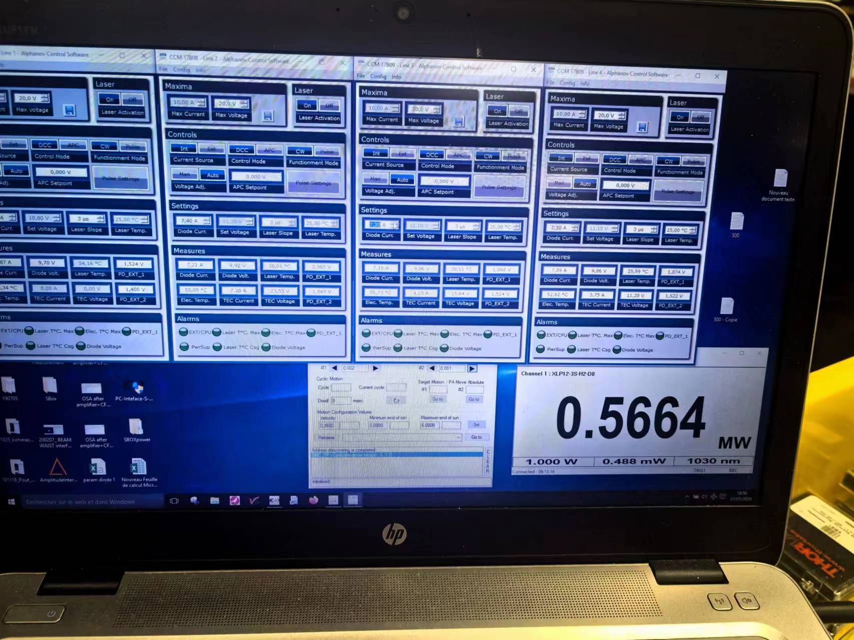
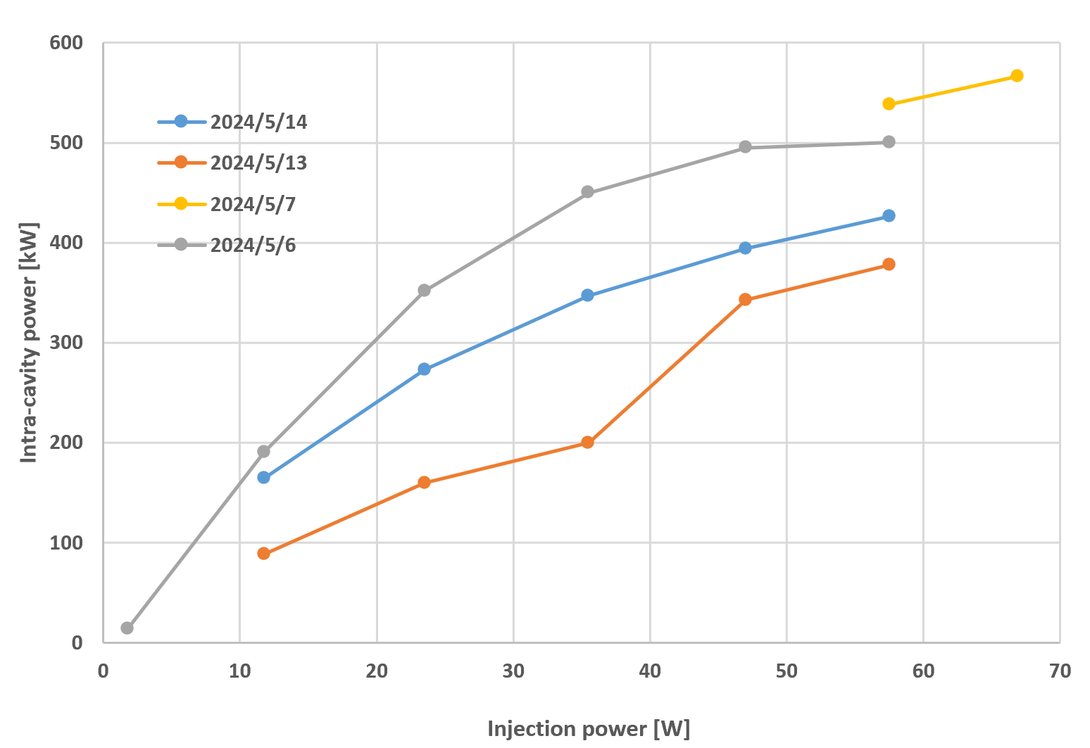
Tue May 7: We moved the D-shaped mirror position at high power, and the intracavity power reached a maximum of 566 kW at 7 A (as Fig 1). The telescopes are the same as on May 6.
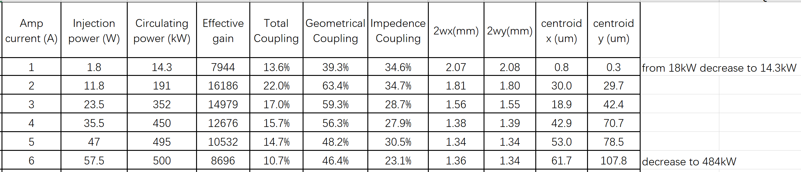
Mon May 13: We moved the two lenses closer to the cavity by 12 cm with the two lenses 20 cm apart. At 5A and 6A, we tried several times to move the concave lens slightly to get higher power. CEP and alignment were optimized after each movement. The best power is shown in Fig. 2 and the table.
Tue May 14: We moved the two lenses far from the cavity ((in the middle of May 13 and before). We tried several times to move the concave lens slightly to get higher power. CEP and alignment were optimized after each movement. The best power is shown in Fig. 2 and the table.
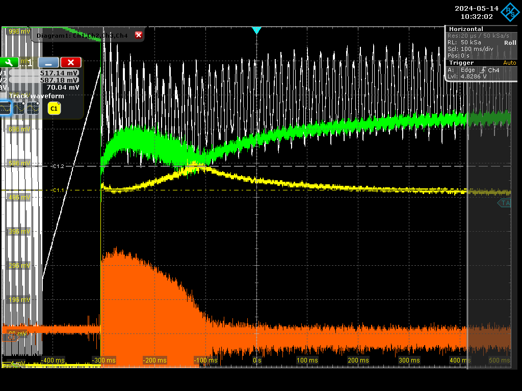
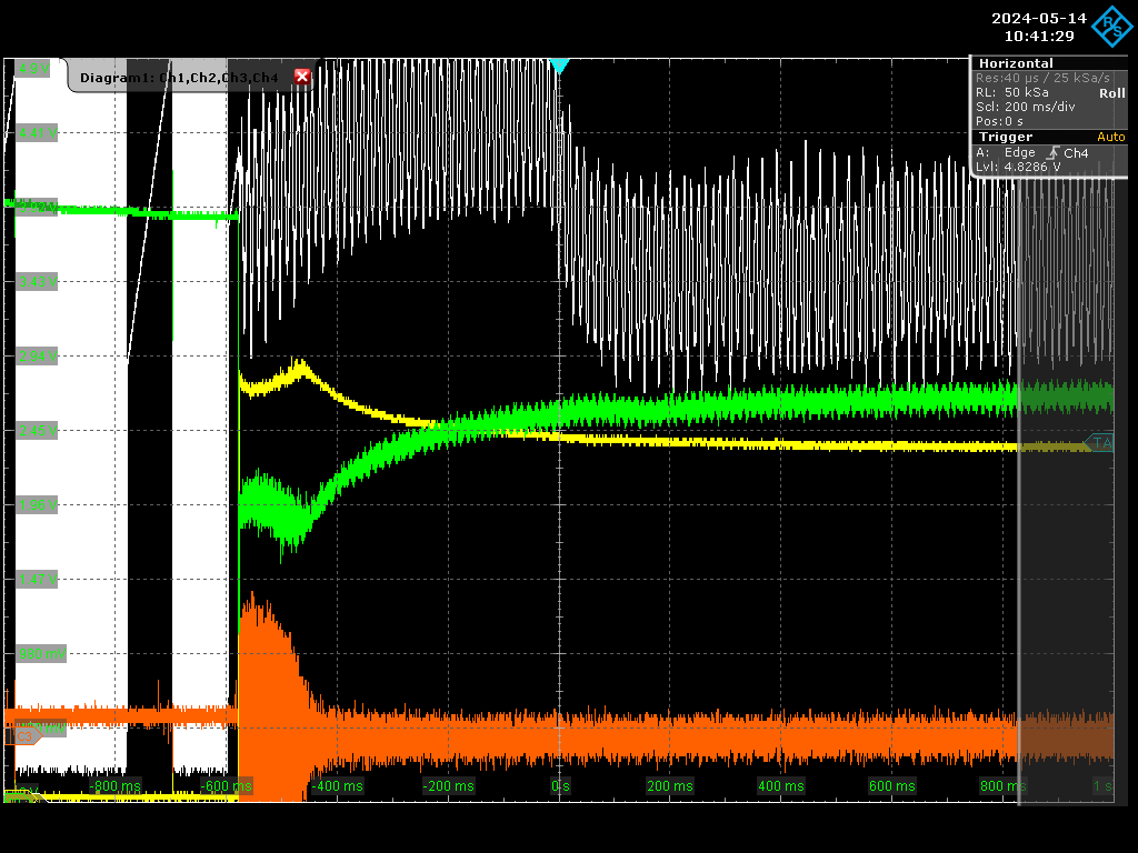
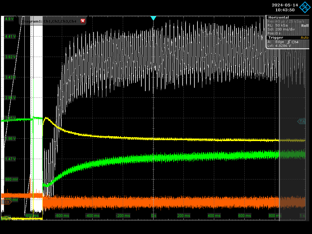
We find a small peak in the transmission at high power when the cavity is just locked (as shown in Figure 4-6 at different powers).
| Xinyi Lu wrote: |
|
here is a Matlab code to try to optimize the telescope for a hot cavity,
taking into account the thermal lens in the coupling mirror.
from that code, one can deduce using the "Gaussian Beam" software (using the attached xml file) an optimized telescope with 100% geometrical coupling @ Pcav = 700kW and absorption in the coatings = 0.6ppm
| Xinyi Lu wrote: |
|
Today, Ronic, Daniele and I redo the high-power 2-mirror cavity experiments, and the results are shown in the table (Figure 1 and Excel 2 ).
- The intracavity power ~500kW can be obtained at 47W injection, but we then have no increase or even a decrease in intracavity power when increasing the injection power, and the coupling is decreasing. It looks like the saturation power of the current device.
- We moved the telescope last week at 2A by moving the concave lens 0.5cm closer to the cavity but almost no change in intracavity power (195kW to 193kW). The telescopes for today's experiment are in the new locations from last week, and we didn't move them today.
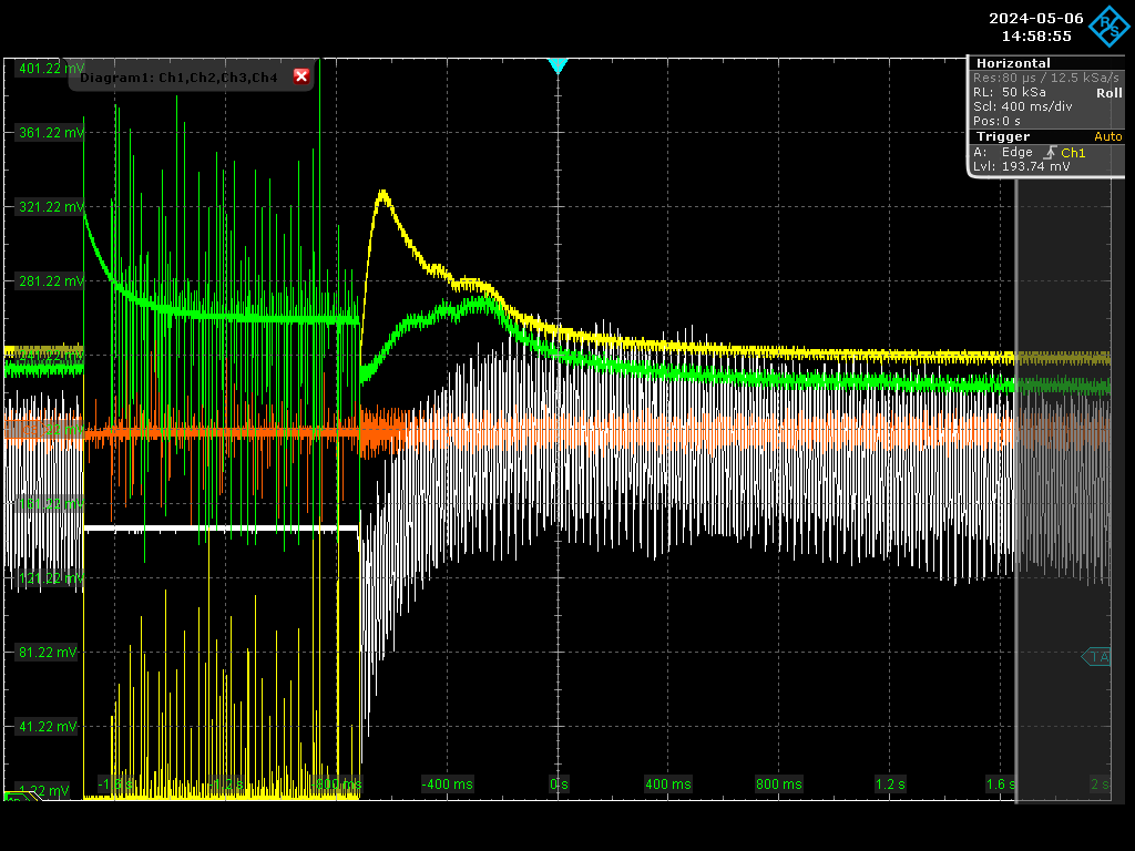
- Figure 3 shows the locking curve at 500kW with some thermal effect changes.
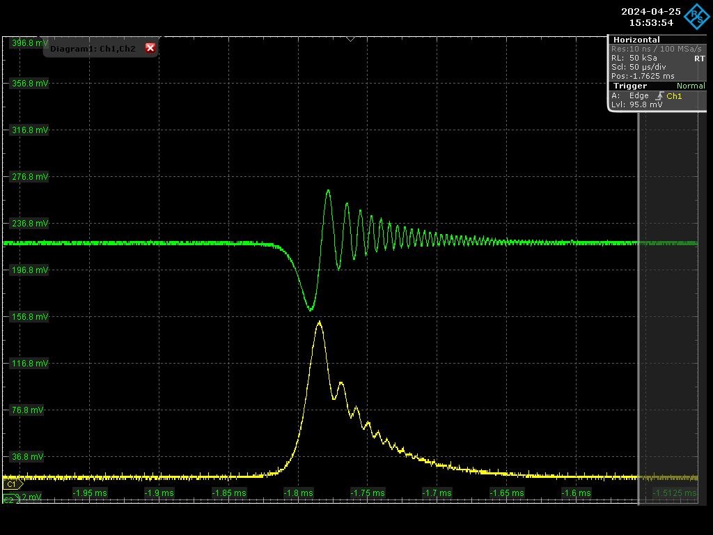
- Figure 4 shows the de-lock and to-lock curves at 14kW.
- The current results may be due to two causes, the thermal lensing effect and the physical change in the mirror coating. It is possible that the transmission of the two mirrors changes with temperature.
- The next plan is to adjust the telescope at 4A to see if we can increase the intracavity power. Meanwhile, do some simulations about dynamic locking, coupling rate, and transmittance.
| Xinyi Lu wrote: |
|
Today, Ronic and I recorded some intracavity power and cavity mode size as shown in Fig. 1.
Coupling was calculated using the locking curve of this overcoupled cavity. Pr/Pi = 1-Cgeo*Cimp, Cimp = 1-|1-2T1/RTL|^2
We can see that the effective gain, coupling, and mode size decrease with increasing power. And the beam is constantly moving.
Tomorrow we will try to optimize the telescope for the high-power hot cavity.
|
|
|
|
| Attachment 1: 7A_566kW.jpg
|
 |
| Attachment 2: high_power_experiments.png
|
 |
| Attachment 3: record_20240506-0514.xlsx
|
| Attachment 4: Screenshot_2024-05-14_1_103202-400kW-6A.png
|
 |
| Attachment 5: Screenshot_2024-05-14_5_104129-377kw-4.75A.png
|
 |
| Attachment 6: Screenshot_2024-05-14_6_104350-300kW-3.5A.png
|
 |
|
221
|
Thu May 16 18:51:17 2024 |
Xinyi Lu | Fixed | info | lasers and optics | Optical room | high-power experiments of 2-mirror cavity |
here is a Matlab code to try to optimize the telescope for a hot cavity,
taking into account the thermal lens in the coupling mirror.
from that code, one can deduce using the "Gaussian Beam" software (using the attached xml file) an optimized telescope with 100% geometrical coupling @ Pcav = 700kW and absorption in the coatings = 0.6ppm
| Xinyi Lu wrote: |
|
Today, Ronic, Daniele and I redo the high-power 2-mirror cavity experiments, and the results are shown in the table (Figure 1 and Excel 2 ).
- The intracavity power ~500kW can be obtained at 47W injection, but we then have no increase or even a decrease in intracavity power when increasing the injection power, and the coupling is decreasing. It looks like the saturation power of the current device.
- We moved the telescope last week at 2A by moving the concave lens 0.5cm closer to the cavity but almost no change in intracavity power (195kW to 193kW). The telescopes for today's experiment are in the new locations from last week, and we didn't move them today.
- Figure 3 shows the locking curve at 500kW with some thermal effect changes.
- Figure 4 shows the de-lock and to-lock curves at 14kW.
- The current results may be due to two causes, the thermal lensing effect and the physical change in the mirror coating. It is possible that the transmission of the two mirrors changes with temperature.
- The next plan is to adjust the telescope at 4A to see if we can increase the intracavity power. Meanwhile, do some simulations about dynamic locking, coupling rate, and transmittance.
| Xinyi Lu wrote: |
|
Today, Ronic and I recorded some intracavity power and cavity mode size as shown in Fig. 1.
Coupling was calculated using the locking curve of this overcoupled cavity. Pr/Pi = 1-Cgeo*Cimp, Cimp = 1-|1-2T1/RTL|^2
We can see that the effective gain, coupling, and mode size decrease with increasing power. And the beam is constantly moving.
Tomorrow we will try to optimize the telescope for the high-power hot cavity.
|
|
|
| Attachment 1: telescope_optimization_for_700kW.pdf
|
| Attachment 2: 2_Mirrors_-_216MHz_-_700kW_cavity_setup.xml
|
<?xml version="1.0" encoding="UTF-8"?>
<!DOCTYPE gaussianBeam>
<gaussianBeam version="1.1">
    <bench id="0">
        <wavelength>1.03e-06</wavelength>
        <leftBoundary>0</leftBoundary>
        <rightBoundary>3</rightBoundary>
        <targetBeam id="0">
            <position>1.884</position>
            <waist>0.0005927</waist>
            <positionTolerance>0.1</positionTolerance>
            <waistTolerance>0.01</waistTolerance>
            <minOverlap>0.98</minOverlap>
            <overlapCriterion>0</overlapCriterion>
        </targetBeam>
        <beamFit id="0">
            <name>Fit0</name>
            <dataType>1</dataType>
            <color>4278190335</color>
            <data id="0">
                <position>0</position>
                <value>0</value>
            </data>
            <data id="1">
                <position>0</position>
                <value>0</value>
            </data>
            <data id="2">
                <position>0</position>
                <value>0</value>
            </data>
        </beamFit>
        <opticsList>
            <inputBeam id="2">
                <waist>0.0001447</waist>
                <index>1</index>
                <M2>1</M2>
                <position>0.189</position>
                <name>w0</name>
                <absoluteLock>1</absoluteLock>
            </inputBeam>
            <lens id="5">
                <focal>0.25</focal>
                <position>1</position>
                <name>L3</name>
                <absoluteLock>0</absoluteLock>
            </lens>
            <lens id="6">
                <focal>-0.15</focal>
                <position>1.25</position>
                <name>L4</name>
                <absoluteLock>0</absoluteLock>
            </lens>
            <lens id="11">
                <focal>0.457</focal>
                <position>1.979</position>
                <name>L4</name>
                <absoluteLock>1</absoluteLock>
            </lens>
            <dielectricSlab id="8">
                <indexRatio>1</indexRatio>
                <width>0.01</width>
                <position>1.979</position>
                <name>D2</name>
                <absoluteLock>1</absoluteLock>
            </dielectricSlab>
            <dielectricSlab id="7">
                <indexRatio>1</indexRatio>
                <width>0.01</width>
                <position>2.6708</position>
                <name>D1</name>
                <absoluteLock>1</absoluteLock>
            </dielectricSlab>
        </opticsList>
    </bench>
    <view id="0" bench="0">
        <horizontalRange>3</horizontalRange>
        <verticalRange>0.009999</verticalRange>
        <origin>0</origin>
        <showTargetBeam id="0">1</showTargetBeam>
    </view>
</gaussianBeam>
|
| Attachment 3: cavity_2M_dynamic_thermal_effect.m
|
clear
clc

c=3e8;
lambda=1030e-9;
Pin=35;
Gcav=20e3;

%% 2M-cavity geometrical setup definition
FSR=216.67e6;           % Free Spectral Range of the FP-cavity
Lrt=c/FSR;              % round trip distance in the FP-cavity
L=Lrt/2;                % distance between mirrors
iR10=0;                 % cold ROC of M1
iR20=1/2.241;           % cold ROC of M2

%% 2M-cavity thermal setup definition
A_Coating=0.6e-6;       % absorption in the coatings
% Heraeus Suprasil 3001 parameters
n_Sup3001=1.45;         % refractive index for Fused Silica
A_Sup3001=0.3e-6;       % 0.3+/-0.2 ppm/cm @ 1064nm
kappa_Sup3001=1.38;     % 1.38 W/m/K @ 20°C    / 1.46W/m/K @ 100°C
alpha_Sup3001=0.6e-6;   % 0.51ppm/K @ 0-100°C / 0.59ppm/K @ 0-300°C
beta_Sup3001=8e-6;      % cf Suprasil 3001 documentation
% Corning 7972 ULE parameters
n_ULE=1.45;             % refractive index for ULE
kappa_ULE=1.31;         % 1.31 W/m/K @ 25°C
alpha_ULE=10e-9;        % Premium grade < 10ppb/K
beta_ULE=11e-6;         % 11.24ppm/K @ 40-60°C / 10.68ppm/K @ 20-40°C

%% 2M-cavity cold mode definition
zw0=iR10*L*(1-iR20*L)/(iR10+iR20-2*L*iR10*iR20);
zr0=sqrt(L*(1-L*iR10)*(1-L*iR20)*(iR10+iR20-L*iR10*iR20))/(iR10+iR20-2*L*iR10*iR20);

% complex radius at z=0 (M1)
q0=-zw0+1i*zr0;
% beam size at z=0 (M1)
wm10=sqrt(lambda/pi/zr0)*abs(q0);
% complex radius at z=L (M2)
qL=L-zw0+1i*zr0;
% beam size at z=L (M2)
wm20=sqrt(lambda/pi/zr0)*abs(qL);

% beam profiler position
Lb=0.67;
% definition of the z-axis
Nz=1e3;
z=linspace(-zr0,L+Lb,Nz);
idm=z<=0;
idp=z>=0 & z<=L;
idb=z>=L;

%% telescope definition
% cold optimization
zwT=zw0;
zrT=zr0;
% hot optimization
zwT=-0.38;
zrT=0.155;
qT=z-zwT+1i*zrT;
wT=sqrt(lambda/pi/zrT)*abs(qT);

%% geometrical coupling definition
C0=4*zrT*zr0/((zwT-zw0)^2+(zrT+zr0)^2);

Nk=200;
Pcav=zeros(1,Nk);
C=C0*ones(1,Nk);
wm1=wm10*ones(1,Nk);
wm2=wm20*ones(1,Nk);
kt=0.05;
iR1th_f=0;
iR2th_f=0;
iR1thl_f=0;
iR2thl_f=0;

figure(1)
clf
hold on
grid on
xlabel('z position (m)')
ylabel('beam size (µm)')
plot(z(idm),wT(idm)*1e6,'r')
ylim([0 900])

for k=1:Nk

    % cavity power
    Pcav(k)=Gcav*C(k)*Pin*(k>1);
    % absorbed power in coatings
    Pa=A_Coating*Pcav(k);
    % thermal ROC for M1 and M2
    iR1th_i=-alpha_Sup3001/(2*pi*kappa_Sup3001*wm1(k)^2)*Pa;
    iR2th_i=-alpha_ULE/(2*pi*kappa_ULE*wm2(k)^2)*Pa;
    % thermal lens for M1 and M2
    iR1thl_i=beta_Sup3001/(2*pi*kappa_Sup3001*wm1(k)^2)*Pa;
    iR2thl_i=-0*beta_ULE/(2*pi*kappa_ULE*wm2(k)^2)*Pa;

    % slow thermal effect simulation
    iR1th_f=iR1th_f+kt*(iR1th_i-iR1th_f);
    iR2th_f=iR2th_f+kt*(iR2th_i-iR2th_f);
    iR1thl_f=iR1thl_f+kt*(iR1thl_i-iR1thl_f);
    iR2thl_f=iR2thl_f+kt*(iR2thl_i-iR2thl_f);

    % total ROC for M1 and M2
    iR1=iR10+iR1th_f;
    iR2=iR20+iR2th_f;
    % total ROC in tranmission for M1 and M2
    iR1t=iR10+iR1thl_f;
    iR2t=iR20+iR2thl_f;

    % cavity mode parameters
    zw=iR1*L*(1-iR2*L)/(iR1+iR2-2*L*iR1*iR2);
    zr=sqrt(L*(1-L*iR1)*(1-L*iR2)*(iR1+iR2-L*iR1*iR2))/(iR1+iR2-2*L*iR1*iR2);
    q0=-zw+1i*zr;
    qL=L-zw+1i*zr;
    q=z-zw+1i*zr;
    w=sqrt(lambda/pi/zr)*abs(q);

    % beam from telescope to cavity
    zwTA=(zwT+2*iR1t*(zrT^2+zwT^2))/(1+4*iR1t*zwT+4*iR1t^2*(zwT^2+zrT^2));
    zrTA=zrT/(1+4*iR1t*zwT+4*iR1t^2*(zwT^2+zrT^2));
    qTA=z-zwTA+1i*zrTA;
    wTA=sqrt(lambda/pi/zrTA)*abs(qTA);

    % beam after the cavity
    zwOUT=(zw+2*iR2t*(zr^2+zw^2))/(1+4*iR2t*zw+4*iR2t^2*(zw^2+zr^2));
    zrOUT=zr/(1+4*iR2t*zw+4*iR2t^2*(zw^2+zr^2));
    qOUT=z-zwOUT+1i*zrOUT;
    wOUT=sqrt(lambda/pi/zrOUT)*abs(qOUT);

    % plots
    plot(z(idp),w(idp)*1e6,'k')
    plot(z(idp),wTA(idp)*1e6,'r')
    %plot(z(idb),wOUT(idb)*1e6,'b')

    % coupling calculation
    if k<Nk
        wm1(k+1)=sqrt(lambda/pi/zr)*abs(q0);
        wm2(k+1)=sqrt(lambda/pi/zr)*abs(qL);
        C(k+1)=4*zrTA*zr/((zwTA-zw)^2+(zrTA+zr)^2);
    end

end

figure(2)
clf
plot(Pcav/1e3)
grid on
ylim([0 max(Pcav/1e3)])
ylabel('cavity power (kW)')

figure(3)
clf
plot(C)
grid on
ylim([0 1])
ylabel('coupling (A.U)')

zwT=(zw-2*iR1t*(zr^2+zw^2))/(1-4*iR1t*zw+4*iR1t^2*(zw^2+zr^2));
zrT=zr/(1-4*iR1t*zw+4*iR1t^2*(zw^2+zr^2));

disp(['waist position for telescope from hot cavity  : ' num2str(zwT) ' m'])
disp(['Rayleigh length for telescope from hot cavity : ' num2str(zrT) ' m'])
|
|
220
|
Mon May 6 18:38:18 2024 |
Xinyi Lu | Fixed | info | lasers and optics | Optical room | high-power experiments of 2-mirror cavity |
Today, Ronic, Daniele and I redo the high-power 2-mirror cavity experiments, and the results are shown in the table (Figure 1 and Excel 2 ).
- The intracavity power ~500kW can be obtained at 47W injection, but we then have no increase or even a decrease in intracavity power when increasing the injection power, and the coupling is decreasing. It looks like the saturation power of the current device.
- We moved the telescope last week at 2A by moving the concave lens 0.5cm closer to the cavity but almost no change in intracavity power (195kW to 193kW). The telescopes for today's experiment are in the new locations from last week, and we didn't move them today.
- Figure 3 shows the locking curve at 500kW with some thermal effect changes.
- Figure 4 shows the de-lock and to-lock curves at 14kW.
- The current results may be due to two causes, the thermal lensing effect and the physical change in the mirror coating. It is possible that the transmission of the two mirrors changes with temperature.
- The next plan is to adjust the telescope at 4A to see if we can increase the intracavity power. Meanwhile, do some simulations about dynamic locking, coupling rate, and transmittance.
| Xinyi Lu wrote: |
|
Today, Ronic and I recorded some intracavity power and cavity mode size as shown in Fig. 1.
Coupling was calculated using the locking curve of this overcoupled cavity. Pr/Pi = 1-Cgeo*Cimp, Cimp = 1-|1-2T1/RTL|^2
We can see that the effective gain, coupling, and mode size decrease with increasing power. And the beam is constantly moving.
Tomorrow we will try to optimize the telescope for the high-power hot cavity.
|
|
| Attachment 1: record_20240506.png
|
 |
| Attachment 2: record20240506.xlsx
|
| Attachment 3: Screenshot_2024-05-06_11_145855-500kW.png
|
 |
| Attachment 4: Screenshot_2024-05-06_1_112931-14kW.png
|
 |
|
219
|
Thu Apr 25 22:12:25 2024 |
Xinyi Lu | Fixed | info | lasers and optics | Optical room | 2 mirror cavity high power experiments |
Today, Ronic and I recorded some intracavity power and cavity mode size as shown in Fig. 1.
Coupling was calculated using the locking curve of this overcoupled cavity. Pr/Pi = 1-Cgeo*Cimp, Cimp = 1-|1-2T1/RTL|^2
We can see that the effective gain, coupling, and mode size decrease with increasing power. And the beam is constantly moving.
Tomorrow we will try to optimize the telescope for the high-power hot cavity.
|
| Attachment 1: record_20240425.png
|
 |
| Attachment 2: Screenshot_2024-04-25_4_155354-155kw.png
|
 |
| Attachment 3: Screenshot_2024-04-25_1_154630-155kw.png
|
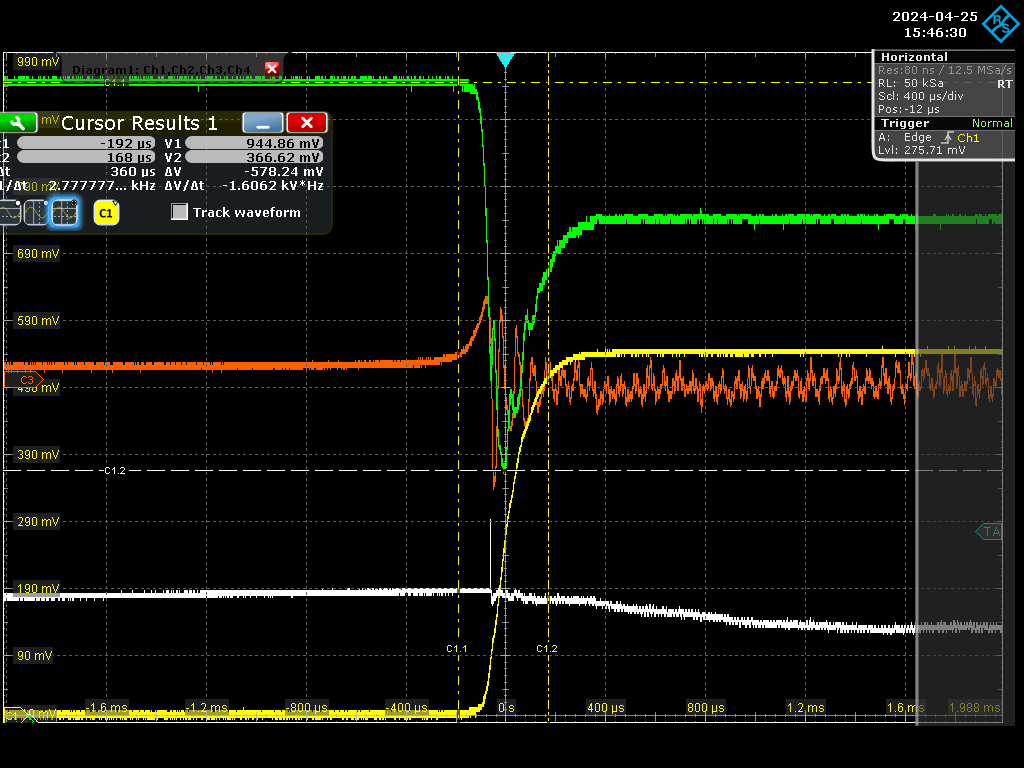 |
| Attachment 4: 60kW_highordermode2.jpg
|
 |
|
218
|
Tue Apr 16 18:38:04 2024 |
Xinyi Lu | Fixed | info | lasers and optics | Optical room | Fiber injection, spectrum and connection of 2nd stage amplifier |
Today, Daniele and I injected the laser into the fiber, installed the telescope, connected the second stage of the amplifier, and obtained resonances.
- The output power of the menhir laser @ 216MHz is 150mW, after CVBG is 28mW , 9.6mW injected into the fiber, and 1.6mW via AOM and EOM. This is not far from the minimum 1mW seed power required by the amplifier.
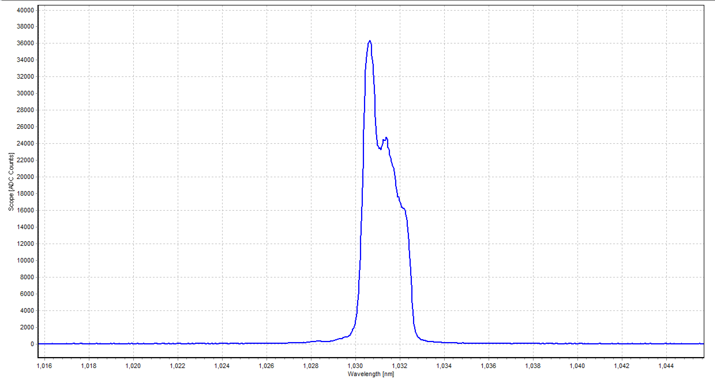
- The spectrum after CVBG is shown in Figure 1.
- The waist of this 2-mirror cavity is 0.583 mm, and the position is on the M1. A set of telescopes is designed and installed as in Figure 2.
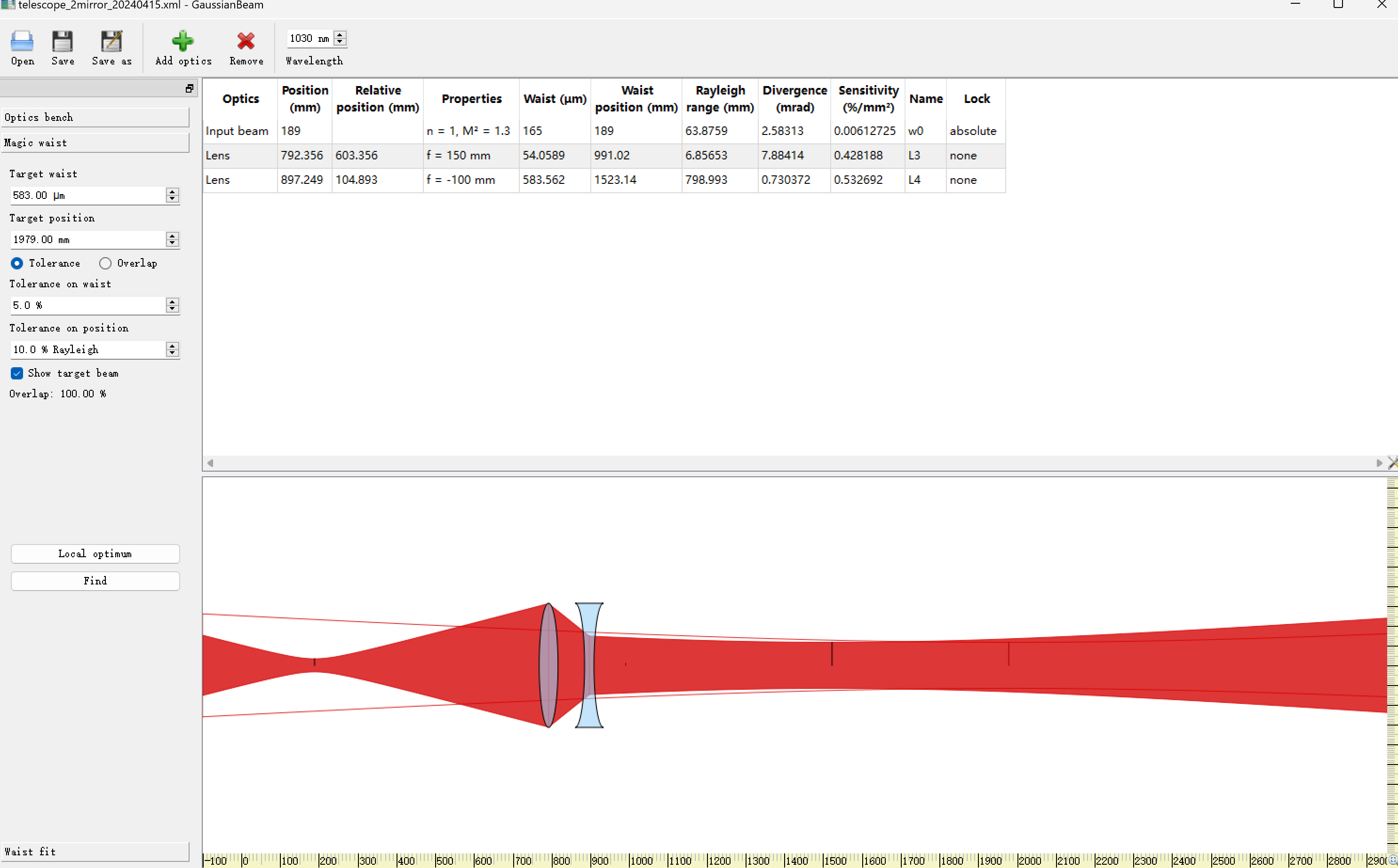
- We injected the second stage of the amplifier into the cavity and obtained fundamental mode. Aurélien and I are trying to lock it. |
| Attachment 1: CVBG_inject_to_fiber.png
|
 |
| Attachment 2: telescope.png
|
 |
|
217
|
Mon Apr 15 18:19:40 2024 |
Xinyi Lu | Fixed | info | lasers and optics | Optical room | Finesse measurement of 2-mirror cavity |
- Today Daniele and I cleaned the spherical mirror by wiping it with alcohol, and the finesse increased to 47k in air.
- After vacuuming, the final finesse is about 45k. The enhancement factor is expected to be 23k.
- Then we tuned the cavity length, FSR = 216.666 MHz. Aurélien helped us to install the menhir laser of 216 MHz.
- Tomorrow we will optimize the optical path and inject the laser into the fiber.
| Xinyi Lu wrote: |
|
Today Viktor and I completed the installation of the two-mirror cavity and managed to lock and measure the finesse.
- The finesse is 36k now (see figure 1). For the designed value of the mirror, the expected finesse is ~50k.
- The diameter of M2 transmission is 1.67 mm,1.65 mm (see figure 2).
- The installation process took a lot of time in orienting the PBS. In addition, we found that the cavity reflected beam and the window reflected beam would interfere (see figure 3). The small spot in the lower right corner is the window reflected light.
- We need to discuss whether the next step is to clean the mirrors or vacuum and move on.
| Xinyi Lu wrote: |
|
Today, Viktor and I started installing the two-mirror cavity.
- Firstly, we cleaned the environment and the dust counter showed good cleanliness
- After opening the cavity we tried to determine the source of the strange spot with a laser detection card and found that the beam was very close to the front edge of the longitudinal D-shaped mirror. In addition there was nothing else strange.
- The setup of the two-mirror cavity is shown in Figure 1. We have to use the menhir laser of 216MHz. The mirrors used are shown in Figure 2.
- We have installed the M2 and will continue the installation tomorrow.
|
|
|
| Attachment 1: finesse_45k.png
|
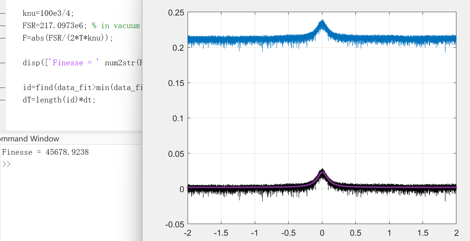 |
|
216
|
Fri Apr 12 17:18:15 2024 |
Xinyi Lu | Fixed | info | lasers and optics | Optical room | Install 2-mirror cavity |
Today Viktor and I completed the installation of the two-mirror cavity and managed to lock and measure the finesse.
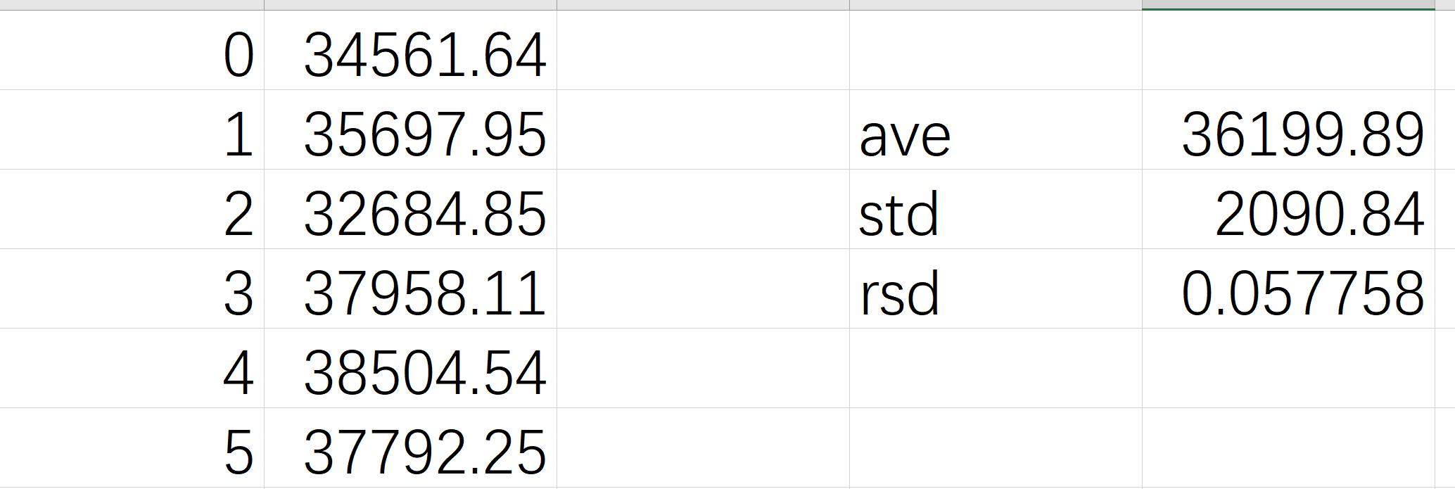
- The finesse is 36k now (see figure 1). For the designed value of the mirror, the expected finesse is ~50k.
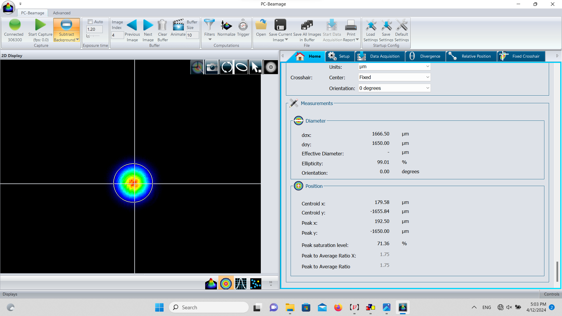
- The diameter of M2 transmission is 1.67 mm,1.65 mm (see figure 2).
- The installation process took a lot of time in orienting the PBS. In addition, we found that the cavity reflected beam and the window reflected beam would interfere (see figure 3). The small spot in the lower right corner is the window reflected light.
- We need to discuss whether the next step is to clean the mirrors or vacuum and move on.
| Xinyi Lu wrote: |
|
Today, Viktor and I started installing the two-mirror cavity.
- Firstly, we cleaned the environment and the dust counter showed good cleanliness
- After opening the cavity we tried to determine the source of the strange spot with a laser detection card and found that the beam was very close to the front edge of the longitudinal D-shaped mirror. In addition there was nothing else strange.
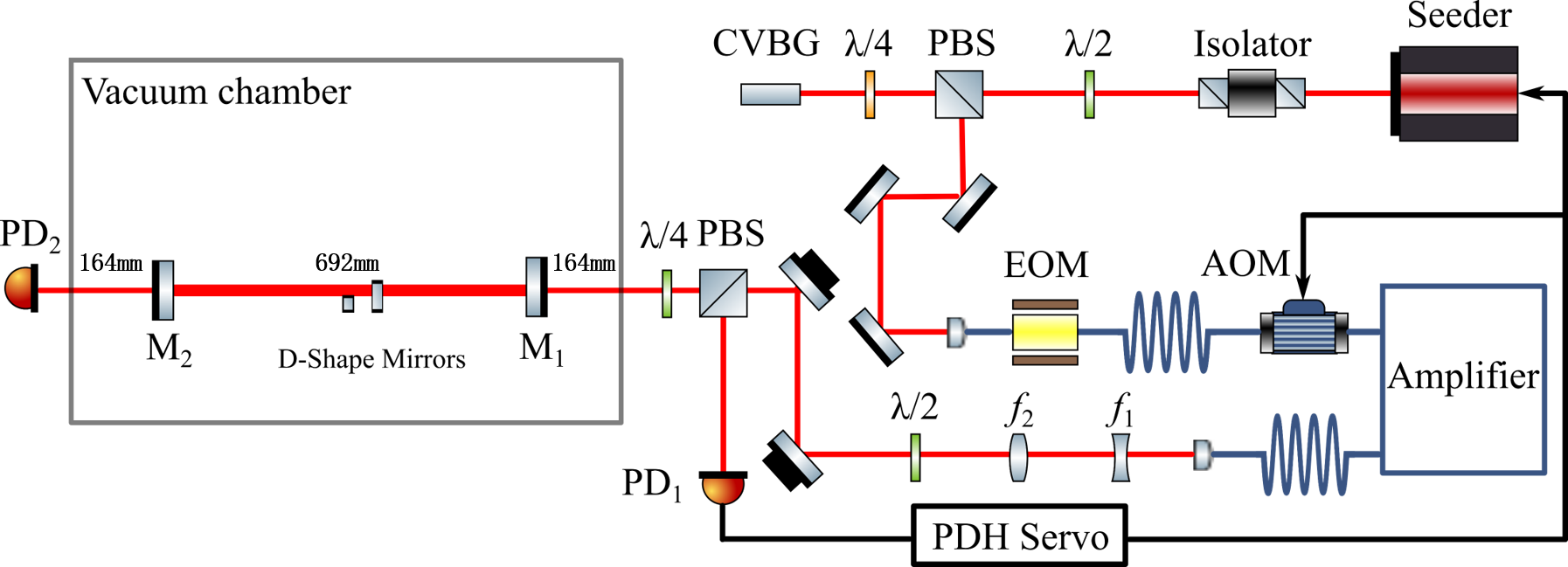
- The setup of the two-mirror cavity is shown in Figure 1. We have to use the menhir laser of 216MHz. The mirrors used are shown in Figure 2.
- We have installed the M2 and will continue the installation tomorrow.
|
|
| Attachment 1: finesse_2mirror.png
|
 |
| Attachment 2: Screenshot_2024-04-12_170357.png
|
 |
| Attachment 3: Screenshot_2024-04-12_145025.png
|
 |
|
215
|
Thu Apr 11 19:09:21 2024 |
Xinyi Lu | Fixed | info | lasers and optics | Optical room | Install 2-mirror cavity |
Today, Viktor and I started installing the two-mirror cavity.
- Firstly, we cleaned the environment and the dust counter showed good cleanliness
- After opening the cavity we tried to determine the source of the strange spot with a laser detection card and found that the beam was very close to the front edge of the longitudinal D-shaped mirror. In addition there was nothing else strange.
- The setup of the two-mirror cavity is shown in Figure 1. We have to use the menhir laser of 216MHz. The mirrors used are shown in Figure 2.
- We have installed the M2 and will continue the installation tomorrow. |
| Attachment 1: 2_mirror_setup.png
|
 |
| Attachment 2: mirrors.png
|
 |
|
214
|
Wed Apr 10 11:35:54 2024 |
Xinyi Lu | Fixed | info | lasers and optics | Optical room | Finesse measurement (35k) |
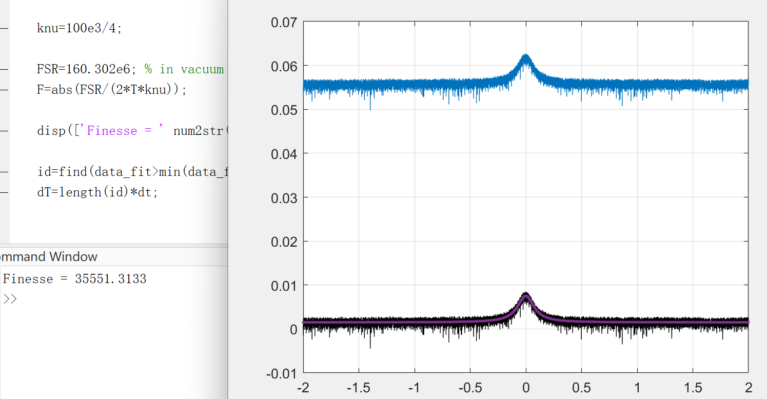
These days, Ronic, Aurélien and I use OEwaves CW laser to measure the finesse of SBOX. We made 5 measurements at 100kHz / 4s sweeps.
The finesse is around 35k (see Figure 1), corresponding to an enhancement factor of 14k.
In our experiments, we only saw up to 9k gain with 70% coupling, corresponding to an enhancement factor of 12.8k.
It could be because of the additional losses introduced by the high power, or the mirror became cleaner after the experiment......
Additionally, we found that the output of the OEwaves CW laser was not a perfect circle, with a depression at the edge of the circle. |
| Attachment 1: 5_measurements_of_finesse.png
|
 |
| Attachment 2: fit.png
|
 |
|
213
|
Tue Apr 9 08:57:22 2024 |
Xinyi Lu | Fixed | info | lasers and optics | Optical room | Different cavity modes & Pulse width |
Additional information:
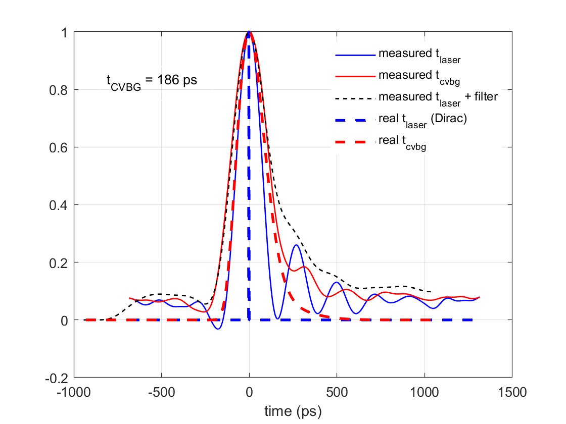
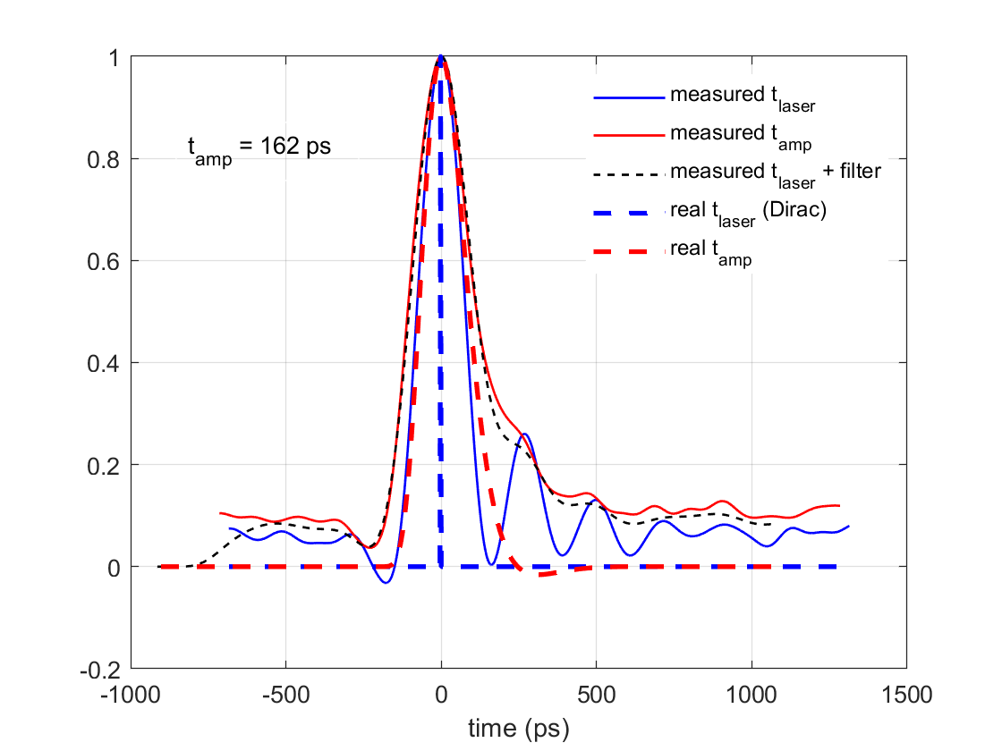
The pulse duration has been performed in RF on a UPD-70-IR2-P photodiode from Alphalas GmbH by carefully deconvoluting the response function of the photodiode measured directly with the sub-picosecond laser beam.
Figure 1 shows the pulse width through the CVBG. Figure 2 is the pulse width when amplified to 10W.
| Xinyi Lu wrote: |
|
- Last week, we obtained three curves of the variation of different cavity modes with power (Fig. 1). By comparing the gain for similar cavity mode sizes, we found that the gain always drops with increasing power.
- We measured the pulse width. The pulse width of the seed laser, after CVBG, amplified at 2A was measured by UPD (rise time < 70ps). Code filtering was performed by comparing the data to reduce the effect of rise time. The final result was t= 186 ps after CVBG and t=162 ps for the amplified at 2A.
- Today we will measure finesse using CW laser.
| Xinyi Lu wrote: |
|
- We re-measured the gain before moving the mirror. Gain ~9000 was achieved at 3A, but as the power increased, the gain dropped and was difficult to optimize. In fact, we found that each day the gain was a little higher than the previous day.
| Amp current (A) |
Injection power (W) |
Circulating power (kW) |
Gain(coupling~0.7) |
Finesse |
| 3 |
23.5 |
213 |
9046 |
33595 |
| 4 |
35.5 |
309 |
8692 |
32933 |
| 5 |
47 |
390 |
8292 |
32165 |
- We then moved the M3 spherical mirror 1.7mm to make the beam size larger and measured the variation in cavity mode size at different powers. (Figure 1, red is the original result and blue is the result for a larger cavity mode). It is clear that the larger the cavity mode, the larger the slope. The new slope of w_y is 7.9mm/MW. Tomorrow we will make the cavity mode smaller (like in Carstens' paper) and compare the three curves.
- It is not simple to compare the gain variations of different cavity modes because it takes more time to optimize the telescope and alignment. Ronic suggested that we could compensate for the cavity mode variation by moving the spherical mirror to see how the gain changes at different powers while keeping the cavity mode unchanged.
- In addition, we measured the spectrum of the menhir laser, after cvgb, amplifier output at 3A (Figure 2). We found that the peak changed from 1031 nm to 1032 nm after CVBG, probably because of the imperfect alignment of CVBG.
| Xinyi Lu wrote: |
|
- Today we moved the position of the D-shaped mirror at 6A. When motor1 (vertical) is 0.2mm away from the spot, the power in the cavity rises from 457kW to 483kW. Gain=8407 is similar to that at low power (Gain=8511). So the D-shaped mirror lost some of the gain in the previous experiments. At 4A and 5A we did not move the D-shaped mirror. (Figure 1)
- At 8A, we got 553 kW inside the cavity for one minute (Figure 2). The pump temperature is higher than yesterday (up to 34°C).
- At 7.5A and 8A, the cavity can remain stably locked, but the power fluctuation in the cavity is so large that it is difficult to optimize the alignment. This may be due to the short time the amplifier was on, the pump temperature, amplifier pointing and power fluctuations, and thermal effects in the cavity....... The amplifier operated differently at different moments.
- We measured the spectrum of the amplified laser. (Figure 3) The peak is 1032.2 nm. We will optimize the alignment and increase the power to optimize this measurement.
- Next arrangement
Thursday: larger laser beam size
Friday: smaller laser beam size
Monday: finesse measurement with CW laser (Firstly check the possibility of measuring with pulsed laser)
| Xinyi Lu wrote: |
|
Yesterday, Ronic, Xing, Qili and I achieved a more stable 520kW power at 7.5A (71W injection) by optimizing the alignment and locking parameters. (Figure 1)
- The cavity can be stable locked when airflow is on. At 7.5A, the pump temperature is about 28℃. The chiller temperature didn't change, to the same 23 ℃ setting. We can try 8A later (75W injection) for a short time;
- Figure 2 demonstrates the cavity mode variation, wy/Pc ~ 1.7 mm/MW, half that of the OL paper (3.3 mm/MW). The thermal deformation of our device is much smaller.
- The experimental data are shown in Figure 3. Figure 4 shows the injection power vs circulating power.
- There are some tests that can be done at the moment. I'll update on the elog after discussing the necessity today. ^_^
|
|
|
|
|
| Attachment 1: t_cvbg.png
|
 |
| Attachment 2: t_amp.png
|
 |