| ID |
Date |
Author |
Status |
Type |
Category |
Location |
Title |
|
93
|
Wed Jun 8 10:47:45 2022 |
Manar Amer | Fixed | report | lasers and optics | Optical room | SBox Alignment |
Closing Series for Alignment.
Beating observed, beam is in the locking stages
| Manar Amer wrote: |
|
The external and internal alignment was redone.
External Alignment : the collimator position moved so in order to have a good start I placed 2 metallic mirrors and did a rough retrace of it's line through the cavity box.
It helped as I did not have to do a lot of adjustment on Ma1 and Ma2 position (new position attached)
Internal Alignment: I replaced the 2 pinholes inside the cavity box with another set where the holes are more symmetric, it shows in the alignment.
Images attached of the beam diffraction pattern after each mirror pinhole.
The injection mirror was placed at the end of the alignment.
Alignment Done !!!!!!!!!!!!!
| Manar Amer wrote: |
|
M2 Sbox changed to spare. Alignment of M2 was redone.
With the help of Ronic , We observe fundamental mode of the cavity with higher order modes. A frequency scan on the piezo was done to find the beating frequency , the shape is elliptical with no clear deformation.
The beam seems to be hitting something, which causes a reflection seen on the beam profiler.
We started a slow scan to improvement of the outside alignment.
At the end of the day, I can only get the TM01 and TM10 modes,
alignment to be continued tomorrow + the scan offset
Note: observation on TM01 and TM10 modes, we clearly see that the beam position is different from the mode center position !!
| Manar Amer wrote: |
|
Yesterday, to find the source of why the mode is deformed, I tried to rotate the mirrors to see if there is a change.
I started with M2 and rotated it by ~ 90 degrees, there is a change in the shape of the beam.(image attached)
Will see if changing M2 to the spare M2 from SBox can fix the issue.
At the end of the day, alignment was lost.
will be redone today while changing M2 mirror.
| Manar Amer wrote: |
|
Today; replaced the M1 SBox mirror with M1 from gamma factory , following the previous alignment.
Removed all mirrors and cleaned them one by one.
Started with no M1, placed M2 did its alignment through M3 pinhole, then placed M3 aligned it through M4 pinhole, then placed M4 aligned it through M1 pinhole.
Placed M1 Gamma factory at the end
Note: mirror is new was not used before, took image on microscope there was no dust in the center, but there was little on the edges (cleaned it using spin-coater)
beating of fundamental mode observed (at M2 transmission) immediately with very higher order modes, slight adjustment on M4 suppressed them.
The beam is not circular and still has some deformation, M1 was changed, so it could be a damaged point at one of the other mirrors (to be investigated tomorrow)!!
No significant damage seen on the other mirrors.
|
Manar Amer wrote:
|
|
Last week In FP cavity we had all SBox mirrors including the damaged M1 mirror.
The beating was observed with just a slight adjustment on M4 alignment.
In addition, it was also observed while driving the piezo of the CW laser.
In the attached image of the beam at transmission point at M2 mirror, the shape of the beam is deformed.
one of the factors could be related to the damaged spot on M1 mirror. The deformation position can also be seen in the higher order modes.
after changing the injection mirror to Gamma factory M1, this deformation should disappear.
| Manar Amer wrote: |
|
Finished the alignment of the SBox with M1 of SBox placed, to be changed to gamma factory mirror later
Observed what seems to be transmission through M2 mirror, to be confirmed. image attached shows it
a PowerPoint attached showing the details of today's work.
| Manar Amer wrote: |
- Adjust the placement of the Irises (done at the start of the day, adjusted at the end when M1 mirror was placed)
- Improvement on the Ma1 and Ma2 (The Alignment Mirrors)
- Improves the alignment a bit. There is an observation where there is no symmetry in the image, concluded to be because of the pinholes that are usually used for the alignment the circle cut is not symmetric (took images on phone of pinholes)
- This explains why, for the pinhole used on M1, we see a little more symmetry than the pinhole used on M2.
-
- Placed M1 mirror from Sbox (with damage spot in the middle), after cleaning it using the spincoater, only used to adjust the injection into the mirror where it will give Horizontal displacement due to the thickness of the mirror.
- Last position of the motors attached
- Installed the 2 dielectric mirrors for the reflection line
- Did a rough alignment for the reflection line to have it exit through the reflection window.
Note about mirrors : They were cleaned a year a go and placed in the boxes. When opened the box and seen under microscope they were very dirty with dust particle
Specially from the back, I believe the boxes have dust in them (to be verified under the UV light / Microscope !!!!!!!! )
| Manar Amer wrote: |
|
Remember to update the position of the reference Irises tomorrow !!!!
| Manar Amer wrote: |
|
After pointers and Advice from Aurélien,
improvement of the beam alignment through M1 and M2 irises was done.
To improve the image on the beam profiler, I cleaned the alignment mirrors and the windows using pure ethanol and optical lens cleaning tissue,
a significant improvement after cleaning the inside of M2 Window. Images have less dust diffraction rings.
Attached new images of the beam:
- New Ma1 and Ma2 motor position
- After M1 pinhole optimized (saturated)
- After M2 and M1 pinhole optimizing (saturated and not)
| Manar Amer wrote: |
|
SBox alignment, using CW laser Koheras power 1 mW
- Finished M1 and M2 alignment using the diffraction patterns seen on the beam profiler, the beam fit is not very good ?? (image taken)
- Positions of Ma1 and Ma2 motors are registered (image taken)
- Placed Fixed 2 irises at M1 window and M2 window (Image taken while both are closed)
- Distance between the collimator and beam profiler ~ 2 m
- Distance between collimator and M1 diaphragm ~ 1 m
- Distance between collimator and M2 diaphragm ~ 1.6 m
| Manar Amer wrote: |
|
Starting with the alignment of the KBox using CW Koheras.
The size of the CW output from the collimator at 1 meter from is ~ 2.4 mm, to be adjusted with lenses to match the cavity !!! (attached image)
For the 2 alignment mirrors, I am only able to control 3 axes for now (motor issue for the fourth to be fixed !!) , Horizontal and vertical for Ma1 and Horizontal for Ma2(closes to injection window).
Started with only irises placed on both the M1 and M2. Placed a beam profiler at the window behind M2 to observe an output beam.
Motors position for the 3 axes and beam shape and position after M2 attached.
|
|
|
|
|
|
|
|
|
|
|
|
|
94
|
Wed Jun 8 10:58:15 2022 |
Manar Amer | Fixed | report | lasers and optics | Optical room | Fundamental Mode TEM00 |
Images of the Transmitted beam at M2 mirror at different days.
The first one was from last week, the second from yesterday.
There is misalignment (drift due to temperature) from the position where the beam was initially. ( reference taken between centers of mode and direct injected beam)
it is most clear in the vertical position.
| Manar Amer wrote: |
|
Adding images from the transmission after the spherical mirrors M3 and M4 window for a resonating mode inside the cavity.
There appears to be some misalignment from the center of the mirror ???
| Manar Amer wrote: |
|
The current setup for the SBox has a beam viewer and 2 photodiodes placed at reflection and transmission.
The CW laser piezoelectric crystal was driven using the lase lock system to observe the 00 mode.
Mode Observed and has no reflection (from what was previously seen)
higher order modes are resonating with 00 mode , example 11 mode (shown in image attached)
the coupling is yet to be seen and measured.
|
|
|
| Attachment 1: 20220530_00_Mode.bmp
|
| Attachment 2: 00_Mode_Beam_Transmitted_Position_drift_due_to_temperature.bmp
|
|
96
|
Wed Jun 8 11:24:35 2022 |
Manar Amer | Fixed | report | lasers and optics | Optical room | Telescope - Spacial Matching |
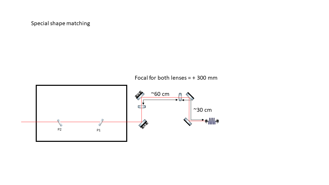
Divergence of the CW beam out of the collimator measured after 1 meter to be
- 2
 x = 0.7425 mrad --> x = 0.37125 mrad x = 0.7425 mrad --> x = 0.37125 mrad
- 2 y = 0.7115 mrad --> y = 0.3575 mrad
two lenses were placed to decrease the diameter of the injected beam |
| Attachment 1: SBox_Spacial_Matching_Telescope.png
|
 |
|
102
|
Wed Jul 6 18:35:38 2022 |
Manar Amer | Fixed | report | lasers and optics | Optical room | Fundamental Mode TEM00 |
Closing series of 00 mode for FSR @ 133.33 MHz
| Manar Amer wrote: |
|
Images of the Transmitted beam at M2 mirror at different days.
The first one was from last week, the second from yesterday.
There is misalignment (drift due to temperature) from the position where the beam was initially. ( reference taken between centers of mode and direct injected beam)
it is most clear in the vertical position.
| Manar Amer wrote: |
|
Adding images from the transmission after the spherical mirrors M3 and M4 window for a resonating mode inside the cavity.
There appears to be some misalignment from the center of the mirror ???
| Manar Amer wrote: |
|
The current setup for the SBox has a beam viewer and 2 photodiodes placed at reflection and transmission.
The CW laser piezoelectric crystal was driven using the lase lock system to observe the 00 mode.
Mode Observed and has no reflection (from what was previously seen)
higher order modes are resonating with 00 mode , example 11 mode (shown in image attached)
the coupling is yet to be seen and measured.
|
|
|
|
|
103
|
Wed Jul 6 18:37:02 2022 |
Manar Amer | Fixed | report | lasers and optics | Optical room | Divergence of the CW beam after collimator |
Closing the series of the telescope for the beam @ 133.33 MHz
|
|
107
|
Fri Jul 8 17:09:26 2022 |
Manar Amer | Fixed | report | lasers and optics | Optical room | Images of ThomX mirrors |
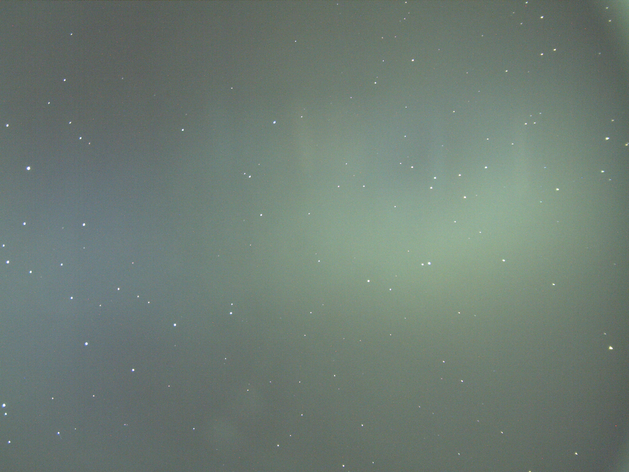
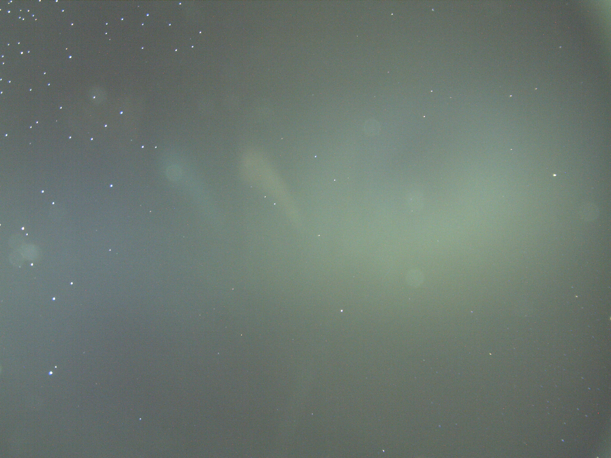
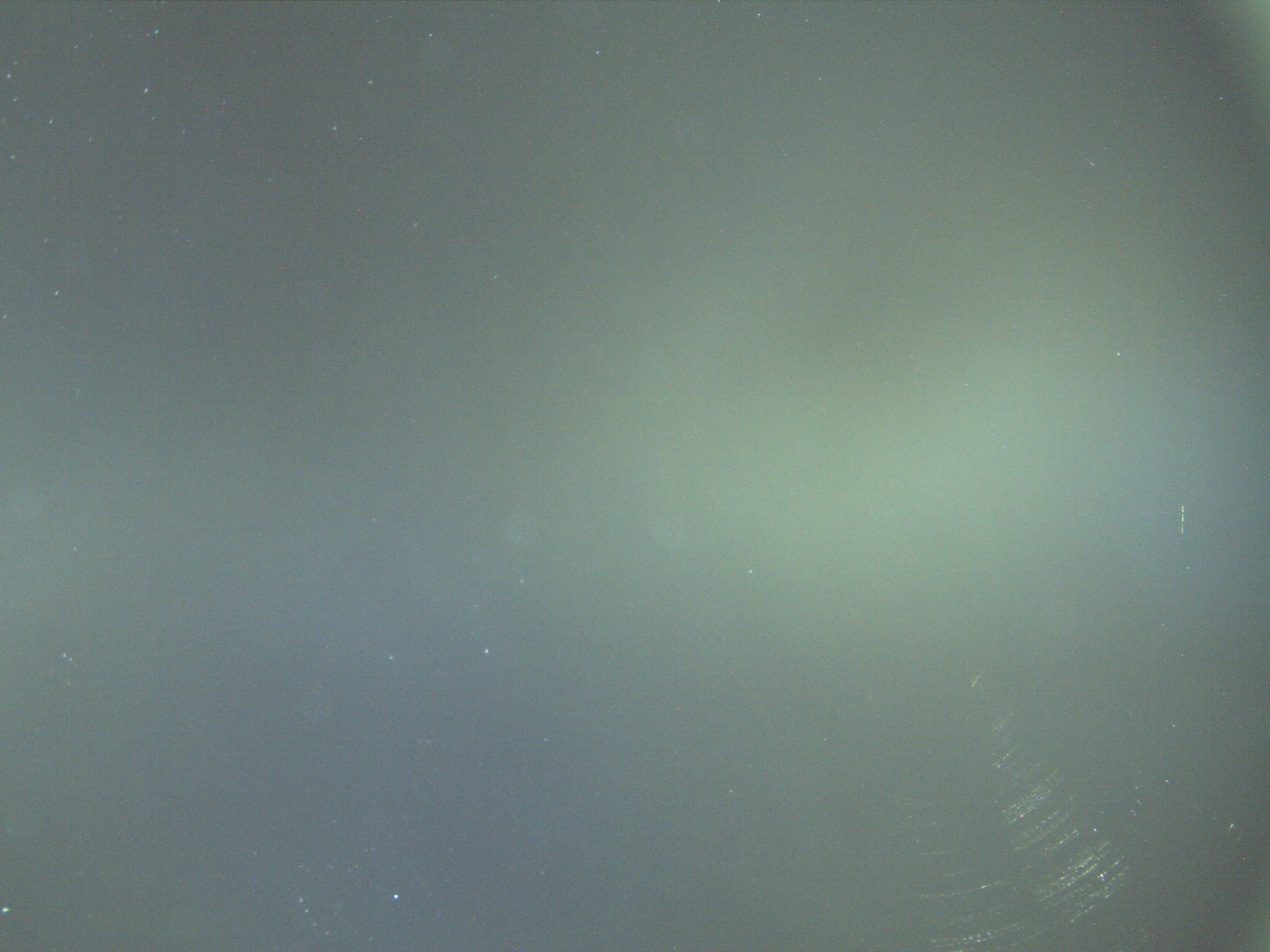
Under the microscope,
the spherical mirrors show the deposit of metal dots on the reflecting surface and not on the back of the mirrors
The mirror with fewer spots near the center was used in the setup.
|
| Attachment 1: ThomX_Spherical_Front_coating.jpg
|
 |
| Attachment 2: ThomX_Spherical_2_Front_coating.jpg
|
 |
| Attachment 3: ThomX_Spherical_back.jpg
|
 |
|
108
|
Fri Jul 8 17:10:44 2022 |
Manar Amer | Fixed | report | lasers and optics | Optical room | Images of ThomX mirrors |
Mirror images in the previous log showing the metal deposit of the coating of the spherical mirrors
(not sent by mail due to large size of images)
| Manar Amer wrote: |
|
Under the microscope,
the spherical mirrors show the deposit of metal dots on the reflecting surface and not on the back of the mirrors
The mirror with fewer spots near the center was used in the setup.
|
|
|
123
|
Mon Aug 8 17:58:32 2022 |
Ronic Chiche | Fixed | info | lasers and optics | Optical room | Pulse duration measurement before and after CVBG (as a strecher) |
I recorded the pulse shape of the MENHIR 216MHz in its fiber injection setup.
the fiber is then connected to the Labbuddy photodiode (~ 15GHz BW) and then to the R&S RTO2000 4GHz scope (~ 100ps rise time).
1) I put a mirror just before the CVBG.
I'm able to get >8mW in the fiber.
as the pulses coming from the laser are not streched, they should be close to Menhir pulse width (~ 200fs).
then, what I measure here is only the pulse response of the measurement system.
2) I remove the mirror before the CVBG to stretch the pulse inside the CVBG
I'm able to get >6mW in the fiber.
the 1st plot is the comparison of the 2 measurements:
in blue, the pulse measurement w/o the CVBG
in red, the pulse measurement with the CVBG
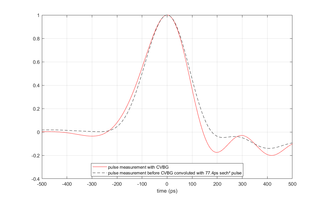
the 2nd plot is the comparison of the pulse streched by the CVBG with the pulse w/o CVBG convoluted with a tp=77.4ps sech² pulse (sech²(t/tp)).
in red, the pulse measurement with the CVBG
in dashed black, the convolution.
(as the spectrum is changed by the CVBG, it is normal that both pulse shapes are not exactly the same).
tp=77.4ps corresponds to t_FWHM = 1.76*77.4ps = 136 ps
both pulses exhibit a FWHM duration of 194 ps.
with the present spectrum after CVBG (see 3rd plot), if the pulse was Fourier Transform limited (no stretched), the product of the FWHM (BW x duration) should be 0.315 (for sech² pulses).
FWHM BW wavelength ~ 1.1nm => FWHM BW ~ 311GHz => FWHM Tau ~ 0.315/311GHz ~ 1 ps
with 136 ps of FWHM duration, one can consider the CVBG has properly streched the pulse. |
| Attachment 1: pulse_measurement_without_and_with_CVBG.png
|
 |
| Attachment 2: pulse_measurement_after_CVBG_compared_with_convolution.png
|
 |
| Attachment 3: SpectrumafterCVBGzoom.png.png
|
 |
|
124
|
Wed Aug 10 12:51:16 2022 |
Ronic Chiche | Fixed | report | lasers and optics | Optical room | "ThomX" CELIA Amplifier commissionning |
The "ThomX" CELIA amplifier is installed on the optical table.
I added all the rubber pieces available between the 2 racks to isolate as best as possible the top rack, which embeds some fans, from the bottom rack from which the laser beam is going out to the FP cavity.
1ST STAGE
-----------------
if I put 1mW (minimum input power) on the input fiber of the amplifier and I switch ON the first stage, one can measure 7mW on the 5% output tap on the front panel.
then it is mandatory to check this power before swtiching ON the other stage.
this 5% output tap on the front panel MUST BE ABOVE 7mW
input power : 1mW => 5% output tap : 7mW => amplifier output : 260µW
with the present setup, I can reach 6.8mW of input power, but the 5% output tap seems to saturate at ~ 8mW.
in this condition, the amplifier output is around 800µW
the SMA connector on the rear panel does not output any signal with the 1st stage ON.
2ND STAGE
-----------------
then, one can switch ON the 2nd stage : amplifier output is around 1.4 W (without any iris or dichroïc mirror).
the SMA connector on the rear panel does not output any signal with the 2nd stage ON. |
|
125
|
Thu Aug 11 12:11:48 2022 |
Ronic Chiche | Fixed | report | lasers and optics | Optical room | "ThomX" CELIA Amplifier commissionning |
Beam size at the amplifier output:
to make this measurement, I switched ON only 1st and 2nd stage.
the dichroïc mirror seems to work the best in reflection at normal AOI !!!
it's strange as most dichroïc mirrors seem to be specified at AOI = 45° ! => to be checked ! => the dichroïc mirror was set on its wrong face !!! => problem solved
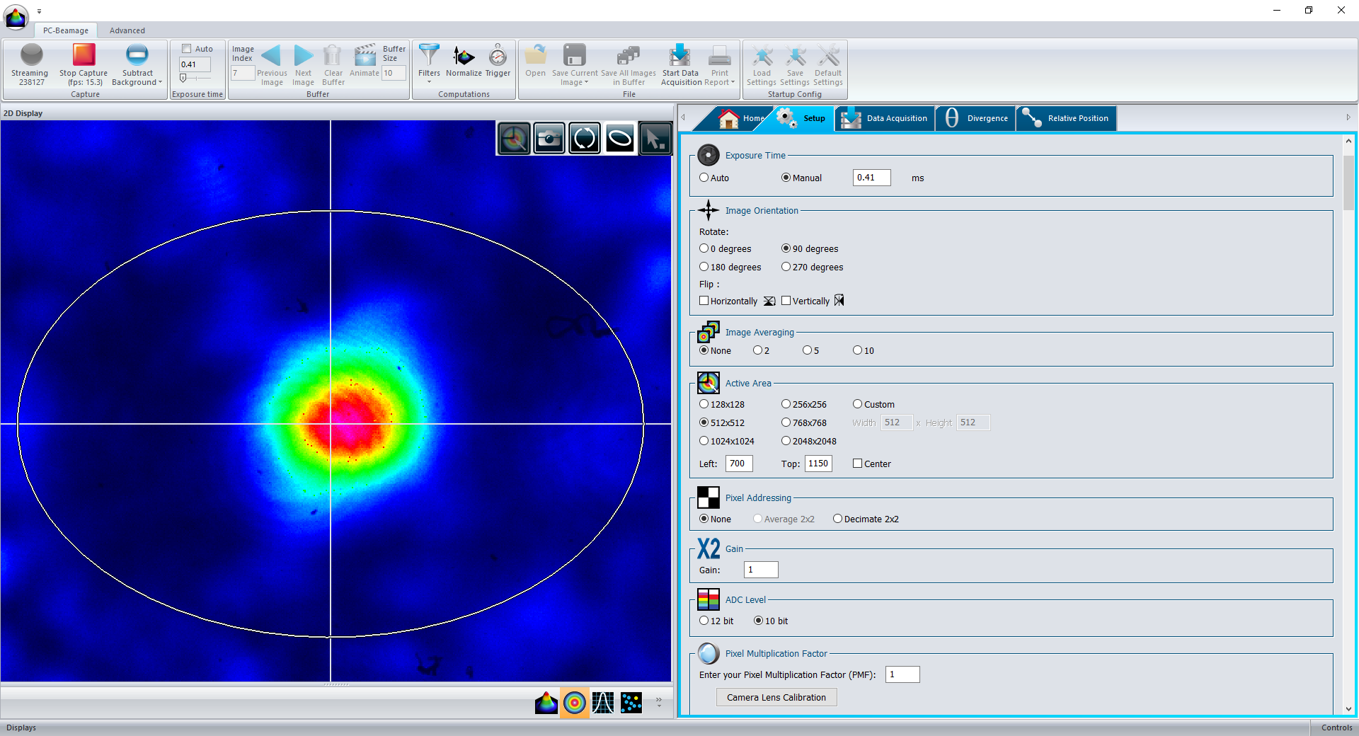
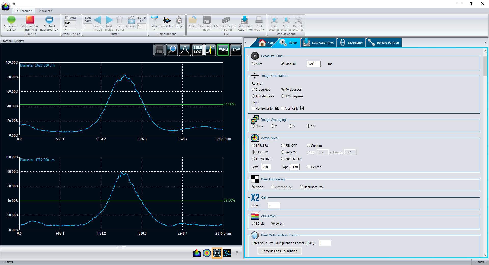
the 2 images correspond to the beam measured at 24cm from the amplifier output.
we cannot use the gaussian fit due to the pump beam shape which perturbate the measurement.
I used the FWHM measurement => DX = 2.6 mm, DY = 1.8mm
Pulse shape model:
dP(x,y,t) = DP * exp( - ln(2) * ( (x/DX_fwhm)² + (y/DY_fwhm)² ) * sech²( t / tp )
=> can we use safely the Newport 20Z40DM.10 mirrors to transport the amplifier beam ?
they are specified for 500 W/cm2 CW and 4 J/cm2 for 10 nsec pulses @ 1064 nm.
- if I am correct, for the previous shape model, the average power is :
Pmoy (W) = 2pi / ln(2) * tp * DP * DX_fwhm * DY_fwhm * Frep
with DP=500W/cm2, DX_fwhm=2.6mm DY_fwhm=1.8mm, tp=77ps, Frep=216MHz => Pmoy = 3.5 W !!!
this means that we should not exceed this average power with these mirrors !?!
- if I am correct, for the previous shape model, the maximal energy density (in the pulse center) is :
DE (J/cm2) = tp * DP => Pmoy = 2pi / ln(2) * DE * DX_fwhm * DY_fwhm * Frep
with DE= 4J/cm2, DX_fwhm=2.6mm DY_fwhm=1.8mm, Frep=216MHz => Pmoy = 366 MW !!!
if one applies a safety factor due to the pulse duration ratio (77ps / 10ns) => Pmoy = 2.8 MW !
this specification seems much less restrictive !
=> can we use safely the Thorlabs BB1-E03 mirrors to transport the amplifier beam ?
they are specified for 10 kW/cm CW (linear power density) and 0.5 J/cm2 for 10 nsec pulses @ 1064 nm.
- the linear power density (LPD) is defined as the average power divided by the beam diameter (1/e²)
LPD = Pmoy / DXY = Pmoy / (1.7 DXY_fwhm) => Pmoy = LPD * 1.7 DXY_fwhm
with LPD=10kW/cm and DY_fwhm=1.8mm => Pmoy = 3 kW
- for maximal energy density:
with DE= 0.5J/cm2, DX_fwhm=2.6mm DY_fwhm=1.8mm, Frep=216MHz => Pmoy = 45 MW !!!
if one applies a safety factor due to the pulse duration ratio (77ps / 10ns) => Pmoy = 350 kW !
| Ronic Chiche wrote: |
|
The "ThomX" CELIA amplifier is installed on the optical table.
I added all the rubber pieces available between the 2 racks to isolate as best as possible the top rack, which embeds some fans, from the bottom rack from which the laser beam is going out to the FP cavity.
1ST STAGE
-----------------
if I put 1mW (minimum input power) on the input fiber of the amplifier and I switch ON the first stage, one can measure 7mW on the 5% output tap on the front panel.
then it is mandatory to check this power before swtiching ON the other stage.
this 5% output tap on the front panel MUST BE ABOVE 7mW
input power : 1mW => 5% output tap : 7mW => amplifier output : 260µW
with the present setup, I can reach 6.8mW of input power, but the 5% output tap seems to saturate at ~ 8mW.
in this condition, the amplifier output is around 800µW
the SMA connector on the rear panel does not output any signal with the 1st stage ON.
2ND STAGE
-----------------
then, one can switch ON the 2nd stage : amplifier output is around 1.4 W (without any iris or dichroïc mirror).
the SMA connector on the rear panel does not output any signal with the 2nd stage ON.
|
|
| Attachment 1: Capture.PNG
|
 |
| Attachment 2: Capture2.PNG
|
 |
|
127
|
Fri Aug 12 11:46:17 2022 |
Ronic Chiche | Fixed | info | lasers and optics | Optical room | OEwaves lock and Finesse measurement |
this morning, I locked the FP cavity with the OEwaves CW laser and the "Fred fiber amplifier" used at 500mA of pump current.
the lock was much more easy than with the Koheras.
I had to change the 10GHz EOM which seems damaged as the modulation depth is very low and does not allow a Finesse measurement by modulation technique.
I changed it by a recently buyed 2GHz EOM... the modulation depth is large enough and we can make the Finesse measurement.
I took several sets of data and the average Finesse is 25.5k ! |
|
128
|
Fri Aug 12 17:48:28 2022 |
Ronic Chiche | Fixed | report | lasers and optics | Optical room | "ThomX" CELIA Amplifier commissionning |
this afternoon, with Fabian, we did some measurements on the 3rd stage.
finally we used the Dichroïc mirror at AOI=45°C as first mirror and a Thorlabs BB1-E03 as 2nd mirror to send the beam to the powermeter.
we put an iris to cut the pump beam part.
with only the 2nd stage ON, the dirchroïc mirror and the iris : P=0.4W
3RD STAGE
-----------------
IT IS MANDATORY TO SWITCH ON THE CHILLER
once the Alphanov software is launched, 4 windows appears on the screeen, one for each diode.
once the chiller temperature reach the set value (23°C in our case), one can start to increase the pump current.
(set "voltage adj." to AUTO)
the TEC of the first diode is not operative, then we decided to stop its current to 4A to avoid a too large temperature (in this condition, the temperature of the diode reach ~45°C !)
the other diodes temperatures are stabilized around 25°C
1A for all diodes => 1 W
2A for all diodes => 10.7 W
3A for all diodes => 22 W
4A for all diodes => 33 W
5A for diodes 2-3-4 => 40.5 W
6A for diodes 2-3-4 => 48.1 W
we stopped the measurement at 6A and we did not notice any change in the optical spectrum
During the optical spectrum measurement we tried to use a NDUV20 Thorlabs reflective filter to reflect the high power beam to the powermeter and let a few power part be transmitted to the spectral measurement.
unfortunatelly, the ND filter coating has been completly removed => DO NOT USE Thorlabs ND filters at high power !
| Ronic Chiche wrote: |
|
Beam size at the amplifier output:
to make this measurement, I switched ON only 1st and 2nd stage.
the dichroïc mirror seems to work the best in reflection at normal AOI !!!
it's strange as most dichroïc mirrors seem to be specified at AOI = 45° ! => to be checked ! => the dichroïc mirror was set on its wrong face !!! => problem solved
the 2 images correspond to the beam measured at 24cm from the amplifier output.
we cannot use the gaussian fit due to the pump beam shape which perturbate the measurement.
I used the FWHM measurement => DX = 2.6 mm, DY = 1.8mm
Pulse shape model:
dP(x,y,t) = DP * exp( - ln(2) * ( (x/DX_fwhm)² + (y/DY_fwhm)² ) * sech²( t / tp )
=> can we use safely the Newport 20Z40DM.10 mirrors to transport the amplifier beam ?
they are specified for 500 W/cm2 CW and 4 J/cm2 for 10 nsec pulses @ 1064 nm.
- if I am correct, for the previous shape model, the average power is :
Pmoy (W) = 2pi / ln(2) * tp * DP * DX_fwhm * DY_fwhm * Frep
with DP=500W/cm2, DX_fwhm=2.6mm DY_fwhm=1.8mm, tp=77ps, Frep=216MHz => Pmoy = 3.5 W !!!
this means that we should not exceed this average power with these mirrors !?!
- if I am correct, for the previous shape model, the maximal energy density (in the pulse center) is :
DE (J/cm2) = tp * DP => Pmoy = 2pi / ln(2) * DE * DX_fwhm * DY_fwhm * Frep
with DE= 4J/cm2, DX_fwhm=2.6mm DY_fwhm=1.8mm, Frep=216MHz => Pmoy = 366 MW !!!
if one applies a safety factor due to the pulse duration ratio (77ps / 10ns) => Pmoy = 2.8 MW !
this specification seems much less restrictive !
=> can we use safely the Thorlabs BB1-E03 mirrors to transport the amplifier beam ?
they are specified for 10 kW/cm CW (linear power density) and 0.5 J/cm2 for 10 nsec pulses @ 1064 nm.
- the linear power density (LPD) is defined as the average power divided by the beam diameter (1/e²)
LPD = Pmoy / DXY = Pmoy / (1.7 DXY_fwhm) => Pmoy = LPD * 1.7 DXY_fwhm
with LPD=10kW/cm and DY_fwhm=1.8mm => Pmoy = 3 kW
- for maximal energy density:
with DE= 0.5J/cm2, DX_fwhm=2.6mm DY_fwhm=1.8mm, Frep=216MHz => Pmoy = 45 MW !!!
if one applies a safety factor due to the pulse duration ratio (77ps / 10ns) => Pmoy = 350 kW !
| Ronic Chiche wrote: |
|
The "ThomX" CELIA amplifier is installed on the optical table.
I added all the rubber pieces available between the 2 racks to isolate as best as possible the top rack, which embeds some fans, from the bottom rack from which the laser beam is going out to the FP cavity.
1ST STAGE
-----------------
if I put 1mW (minimum input power) on the input fiber of the amplifier and I switch ON the first stage, one can measure 7mW on the 5% output tap on the front panel.
then it is mandatory to check this power before swtiching ON the other stage.
this 5% output tap on the front panel MUST BE ABOVE 7mW
input power : 1mW => 5% output tap : 7mW => amplifier output : 260µW
with the present setup, I can reach 6.8mW of input power, but the 5% output tap seems to saturate at ~ 8mW.
in this condition, the amplifier output is around 800µW
the SMA connector on the rear panel does not output any signal with the 1st stage ON.
2ND STAGE
-----------------
then, one can switch ON the 2nd stage : amplifier output is around 1.4 W (without any iris or dichroïc mirror).
the SMA connector on the rear panel does not output any signal with the 2nd stage ON.
|
|
|
|
132
|
Fri Aug 19 16:31:11 2022 |
Manar Amer | Fixed | report | lasers and optics | Optical room | Amplifier output Beam Profile |
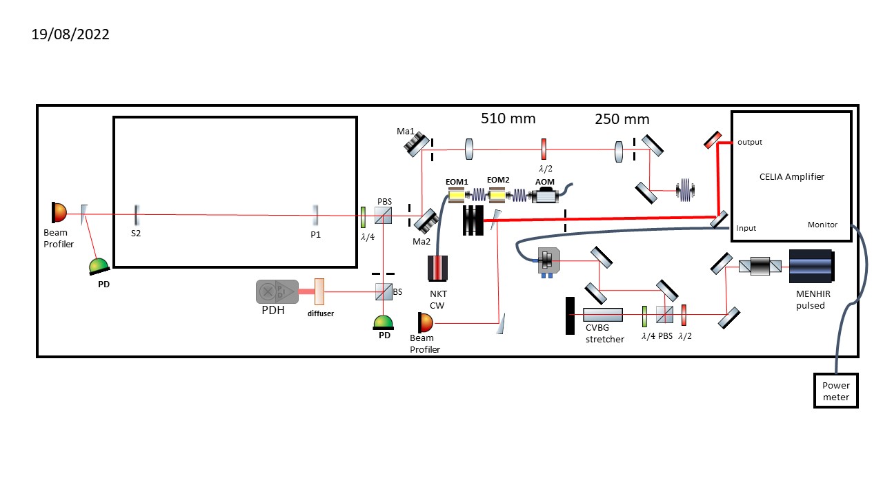
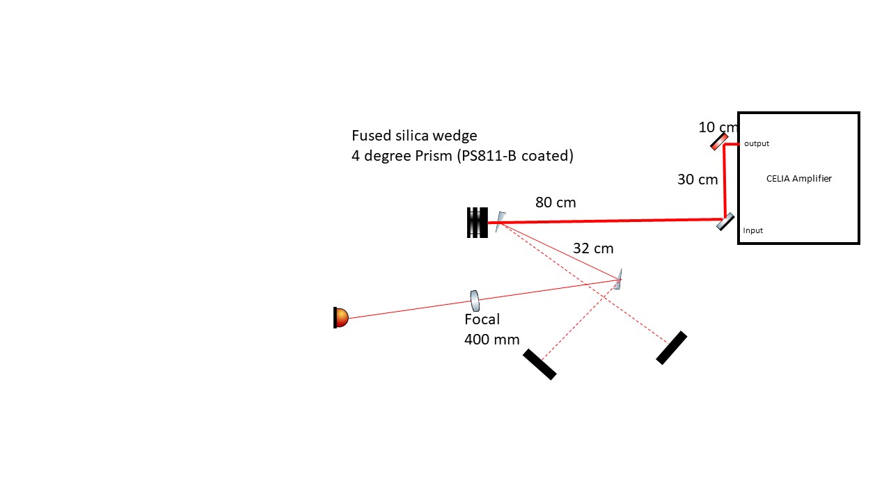
In preparation to measure the output beam profile from the amplifier at high power, I have placed two wedge mirrors just before the beam dump to be able to extract the beam.
One of the wedges was taken from ThomX bunker, also the HR and AR mirrors were taken to plic room in case we might need them
an updated setup is attached |
| Attachment 1: 20220819_Setup.jpg
|
 |
|
133
|
Fri Aug 19 16:36:18 2022 |
Manar Amer | Fixed | report | lasers and optics | Optical room | Telescope / amplifier output |
The previous Sbox telescope was dismantled and the mechanical components cleaned.
its lenses are still in the mounts, it looks that two of them are spherical and two are cylindrical
2 are -100 mm and 2 are +150 mm, there is also a box containing fused silica lenses that could be used.
Note: at high power use only fused silica lenses not BK7 type
|
|
134
|
Mon Aug 22 18:38:03 2022 |
Manar Amer | Fixed | report | lasers and optics | Optical room | Telescope / amplifier output |
Beam divergence was measured using a method called "Focal Length Divergence Measurement Method"
Where a lens of a known focal length is placed on the beam path and the beam waist is measured at the focal distance using a beam profiler.
We ramped the power up to 10 W
for a focal length = 400 mm,
we measured a FWHM = 2.1 mm,
corresponding to a divergence = 4.45 mrad (edit : wrong software use)
for comparison, we measured the FWHM 8.1 mm @ 1.55 m and extracted the divergence directly 4.46 mrad (edit : this measurement is wrong - wrong use of the software)
Note: better to use a lens of a focal lens higher than 100 mm (to reduce the error in the distance measured)
| Manar Amer wrote: |
|
The previous Sbox telescope was dismantled and the mechanical components cleaned.
its lenses are still in the mounts, it looks that two of them are spherical and two are cylindrical
2 are -100 mm and 2 are +150 mm, there is also a box containing fused silica lenses that could be used.
Note: at high power use only fused silica lenses not BK7 type
|
|
| Attachment 1: Focal_length_divergence_method.pdf
|
| Attachment 2: Beam_Profile_at_high_power_.jpg
|
 |
| Attachment 3: SBOX_CELIA_AMPLIFIER_Divergence_measurement.pdf
|
|
135
|
Mon Aug 22 18:39:13 2022 |
Manar Amer | Fixed | report | lasers and optics | Optical room | Amplifier output Beam Profile |
Beam divergence after amplifier 4.46 mrad
| Manar Amer wrote: |
|
In preparation to measure the output beam profile from the amplifier at high power, I have placed two wedge mirrors just before the beam dump to be able to extract the beam.
One of the wedges was taken from ThomX bunker, also the HR and AR mirrors were taken to plic room in case we might need them
an updated setup is attached
|
|
|
136
|
Tue Aug 23 17:37:38 2022 |
Manar Amer | Fixed | report | lasers and optics | Optical room | Telescope / amplifier output |
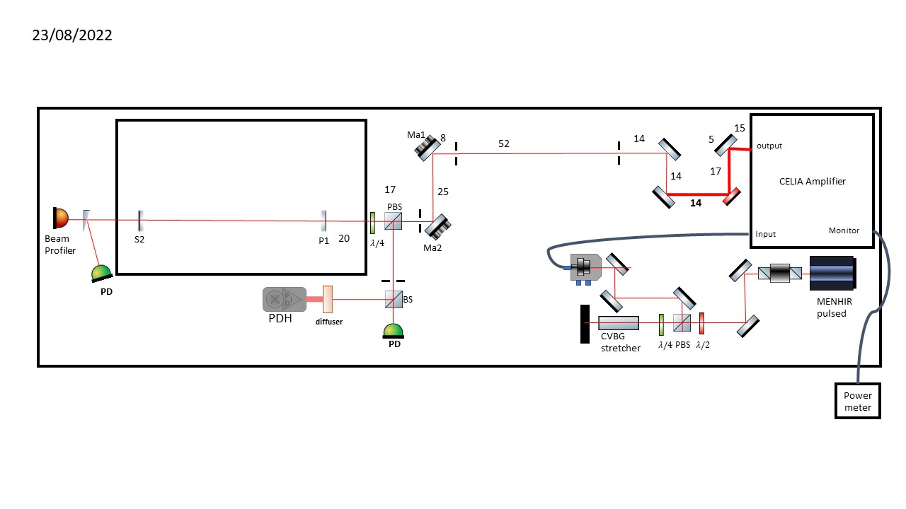
I placed a periscope to adjust the high of the beam from the amplifier output from ~ 10 cm from the table to ~ 15 cm
a dichroic mirror placed after it to reject the pump laser, all the mirrors on the path to the cavity were replaced with dielectric mirrors BB01-E03
the length of the path from the amplifier output to the cavity coupling mirror ~ 2 meters
setup defines the different optics placed in the path
Note: the beam goes all the way to the cavity, put it is not yet optimized to the irises.
| Manar Amer wrote: |
|
Beam divergence was measured using a method called "Focal Length Divergence Measurement Method"
Where a lens of a known focal length is placed on the beam path and the beam waist is measured at the focal distance using a beam profiler.
We ramped the power up to 10 W
for a focal length = 400 mm,
we measured a FWHM = 2.1 mm,
corresponding to a divergence = 4.45 mrad (edit : wrong software use)
for comparison, we measured the FWHM 8.1 mm @ 1.55 m and extracted the divergence directly 4.46 mrad (edit : this measurement is wrong - wrong use of the software)
Note: better to use a lens of a focal lens higher than 100 mm (to reduce the error in the distance measured)
| Manar Amer wrote: |
|
The previous Sbox telescope was dismantled and the mechanical components cleaned.
its lenses are still in the mounts, it looks that two of them are spherical and two are cylindrical
2 are -100 mm and 2 are +150 mm, there is also a box containing fused silica lenses that could be used.
Note: at high power use only fused silica lenses not BK7 type
|
|
|
| Attachment 1: 20220823_setup.jpg
|
 |
|
137
|
Wed Aug 24 10:39:58 2022 |
Manar Amer | Fixed | report | lasers and optics | Optical room | Telescope / amplifier output |
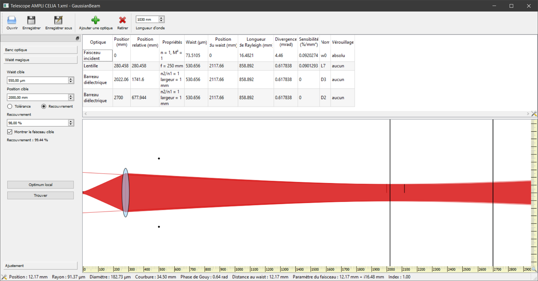
Here is a view of beam propagation in the optical software : GaussianBeam
the red filled shape is the model of the CELIA amplifier beam propagation with a divergence of 4.46 mrad
(the 2 black dots is the measurement of the beam size without any lens to change the beam propagation).
the 2 black lines have been put at the input and output cavity mirrors position relative to the CELIA amplifier position, respectively 2m and 2.7m roughly.
the cavity mode radius should be 0.55mm and 0.7mm respectively.
the cavity mode shape is represented by the 2 red lines (very close to the red filled shape which is the beam).
the most simple working telescope could be a +250 lens at 280mm from the CELIA amplifier.
it gives a beam radius of 0.53mm at the input mirror and 0.64mm at the output mirror.
the overlapping is more than 99%
the 2nd file is the GaussianBeam file.
| Manar Amer wrote: |
|
I placed a periscope to adjust the high of the beam from the amplifier output from ~ 10 cm from the table to ~ 15 cm
a dichroic mirror placed after it to reject the pump laser, all the mirrors on the path to the cavity were replaced with dielectric mirrors BB01-E03
the length of the path from the amplifier output to the cavity coupling mirror ~ 2 meters
setup defines the different optics placed in the path
Note: the beam goes all the way to the cavity, put it is not yet optimized to the irises.
| Manar Amer wrote: |
|
Beam divergence was measured using a method called "Focal Length Divergence Measurement Method"
Where a lens of a known focal length is placed on the beam path and the beam waist is measured at the focal distance using a beam profiler.
We ramped the power up to 10 W
for a focal length = 400 mm,
we measured a FWHM = 2.1 mm,
corresponding to a divergence = 4.45 mrad (edit : wrong software use)
for comparison, we measured the FWHM 8.1 mm @ 1.55 m and extracted the divergence directly 4.46 mrad (edit : this measurement is wrong - wrong use of the software)
Note: better to use a lens of a focal lens higher than 100 mm (to reduce the error in the distance measured)
| Manar Amer wrote: |
|
The previous Sbox telescope was dismantled and the mechanical components cleaned.
its lenses are still in the mounts, it looks that two of them are spherical and two are cylindrical
2 are -100 mm and 2 are +150 mm, there is also a box containing fused silica lenses that could be used.
Note: at high power use only fused silica lenses not BK7 type
|
|
|
|
| Attachment 1: Capture.PNG
|
 |
| Attachment 2: Telescope_AMPLI_CELIA_1.xml
|
<?xml version="1.0" encoding="UTF-8"?>
<!DOCTYPE gaussianBeam>
<gaussianBeam version="1.1">
    <bench id="0">
        <wavelength>1.03e-06</wavelength>
        <leftBoundary>-0.1</leftBoundary>
        <rightBoundary>5</rightBoundary>
        <targetBeam id="0">
            <position>2</position>
            <waist>0.00055</waist>
            <positionTolerance>0.1</positionTolerance>
            <waistTolerance>0.05</waistTolerance>
            <minOverlap>0.98</minOverlap>
            <overlapCriterion>1</overlapCriterion>
        </targetBeam>
        <beamFit id="0">
            <name>Fit6</name>
            <dataType>1</dataType>
            <color>0</color>
            <data id="0">
                <position>0.5</position>
                <value>0.00444</value>
            </data>
            <data id="1">
                <position>0</position>
                <value>0</value>
            </data>
            <data id="2">
                <position>0</position>
                <value>0</value>
            </data>
        </beamFit>
        <opticsList>
            <inputBeam id="2">
                <waist>7.35105e-05</waist>
                <index>1</index>
                <M2>1</M2>
                <position>0</position>
                <name>w0</name>
                <absoluteLock>1</absoluteLock>
            </inputBeam>
            <lens id="24">
                <focal>0.25</focal>
                <position>0.280458</position>
                <name>L7</name>
                <absoluteLock>0</absoluteLock>
            </lens>
            <dielectricSlab id="26">
                <indexRatio>1</indexRatio>
                <width>0.001</width>
                <position>2.02206</position>
                <name>D3</name>
                <absoluteLock>0</absoluteLock>
            </dielectricSlab>
            <dielectricSlab id="23">
                <indexRatio>1</indexRatio>
                <width>0.001</width>
                <position>2.7</position>
                <name>D2</name>
                <absoluteLock>0</absoluteLock>
            </dielectricSlab>
        </opticsList>
    </bench>
    <view id="0" bench="0">
        <horizontalRange>3</horizontalRange>
        <verticalRange>0.01</verticalRange>
        <origin>0</origin>
        <showTargetBeam id="0">1</showTargetBeam>
    </view>
</gaussianBeam>
|
|
138
|
Wed Aug 24 10:45:24 2022 |
Manar Amer | Fixed | report | lasers and optics | Optical room | 2 Mirror Setup @ 216.6 MHz |
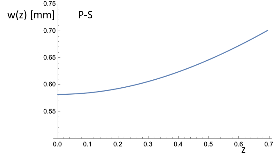
Adding information about the 2 mirror cavity setup (plan - spherical) that is currently installed.
From Aurélien at the start of the manipulation.
@ 0 is where the injection mirror is located
| Manar Amer wrote: |
|
The SBox cavity setup was changed to have only 2 mirrors M1 plane and M2 spherical, both from ThomX
Distance between the mirror ~ 72 cm , increased from 70 cm to take into account the thickness of the ThomX mirrors
Two lenses (300 mm @ 50 cm , 200 @ 104 cm) were placed to have the beam radius ~ 0.55 mm.
The cavity was locked with a coupling of 60 %, for Finesse measurement the sweep was taken over 100 KHz of 2 seconds.
FSR ~ 210.00 MHz, line width ~ 8.56 KHz, Finesse ~ 24 500 .
|
|
| Attachment 1: manip2miroirs.pptx
|
| Attachment 2: 2mirror_plan_shperical_beam_size.png
|
 |
|
139
|
Tue Aug 30 17:48:39 2022 |
Ronic Chiche | Fixed | info | lasers and optics | Optical room | 2nd stage CELIA amplifier |
today, we measured the 2nd stage CELIA amplifier pump wavelength : 970-990 nm |
| Attachment 1: 2nd_stage_pump_wavelength.jpg
|
 |