| ID |
Date |
Author |
Status |
Type |
Category |
Location |
Title |
|
112
|
Tue Jul 12 10:19:30 2022 |
Manar Amer | Fixed | report | lasers and optics | detectors and electronics | Optical room | FSR change & Finesse Measurements |
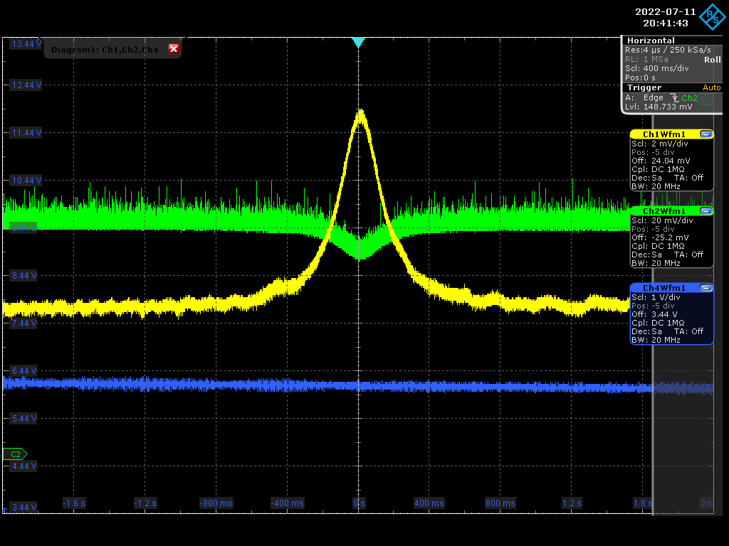
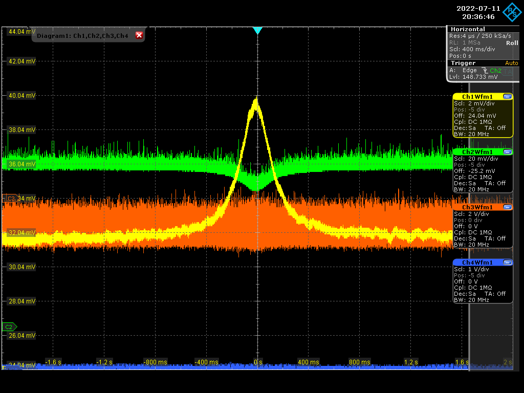
Yesterday evening the cavity was Vacuum pumped up to pressure of 5.5*10^-2 and locked
changed FSR to be 216.662 MHz and alignment a little and measured the Finesse
in Vacuum we have average Finesse = 30341.6265
FWHM (KHz) = 7.0592
Finesse = 30692.1961
FWHM (KHz) = 7.2186
Finesse = 30014.556
FWHM (KHz) = 7.1051
Finesse = 30493.7635
FWHM (KHz) = 7.1079
Finesse = 30481.9812
FWHM (KHz) = 7.1413
Finesse = 30339.2695
FWHM (KHz) = 7.1624
Finesse = 30249.776
FWHM (KHz) = 7.0239
Finesse = 30846.2719
FWHM (KHz) = 7.2614
Finesse = 29837.6477
FWHM (KHz) = 7.1935
Finesse = 30119.1768
| Manar Amer wrote: |
|
The FSR of the 2 mirror (plan-spherical) Cavity was adjusted from 210 MHz to reach 216.643 MHz
it was done by having two reference irises, one at the injection point and one at the reflection
then changing the position of injection plan mirror to slightly closer distance and monitoring the reflection on the oscilloscope to be max.
The cavity modes were still seen, and we had to only improve the injection alignment after.
Me and Ronic locked in air and measured the Finesse, which was bigger by ~ 20%
average Finesse = 30208.53614
FWHM (KHz) = 7.0179
Finesse = 30869.9522
FWHM (KHz) = 7.1257
Finesse = 30403.005
FWHM (KHz) = 7.1287
Finesse = 30390.4014
FWHM (KHz) = 7.2884
Finesse = 29724.5531
FWHM (KHz) = 7.3055
Finesse = 29654.769
| Manar Amer wrote: |
|
Update for Finesse measurement, The cavity was put under vacuum ~ 1.1*10^-1 mbar
and the alignment and coupling improved.
FSR = 210.1 MHz
Average Finesse = 25686.46222
FWHM (KHz) = 8.2387
Finesse = 25501.5659
FWHM (KHz) = 8.2028
Finesse = 25613.2858
FWHM (KHz) = 8.0978
Finesse = 25945.3289
FWHM (KHz) = 8.1744
Finesse = 25702.3142
FWHM (KHz) = 8.1847
Finesse = 25669.8163
Concluded from Ronic's calculations, this could be the maximum finesse we might be able to obtain with this setup
with Gain ~ 8000
On Monday we adjust the frequency to match 2160.66 MHz and lock the Pulsed,
at the same time start we start with the CELIA amplifier.
| Manar Amer wrote: |
|
The cavity was realigned using irises instead of pinholes, gave a better alignment.
The inside of the box, the spherical and the injection mirror were cleaned and placed back inside the box.
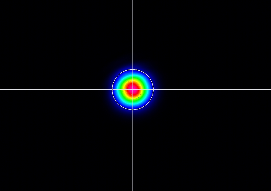
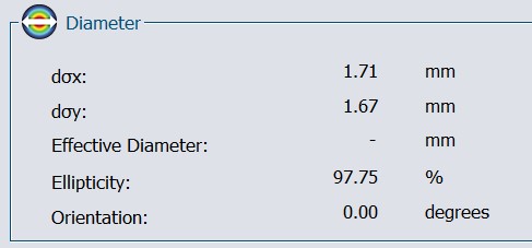
we see beating of fundamental mode, previously at the transmission point we placed a wedge to split the beam which resulted in an elliptical mode
we removed it and placed a very thin beam splitter, the beam is circular now.
The cavity was locked in air at a coupling of ~ 60-70 %
Finesse and line width measured five readings with a Finesse average 25095.08884 of a Gain ~ 8000
FWHM (KHz) = 8.2928
Finesse = 25323.0544
FWHM (KHz) = 7.9202
Finesse = 26514.4395
FWHM (KHz) = 8.5834
Finesse = 24465.8636
FWHM (KHz) = 8.4571
Finesse = 24831.2419
FWHM (KHz) = 8.6275
Finesse = 24340.8448
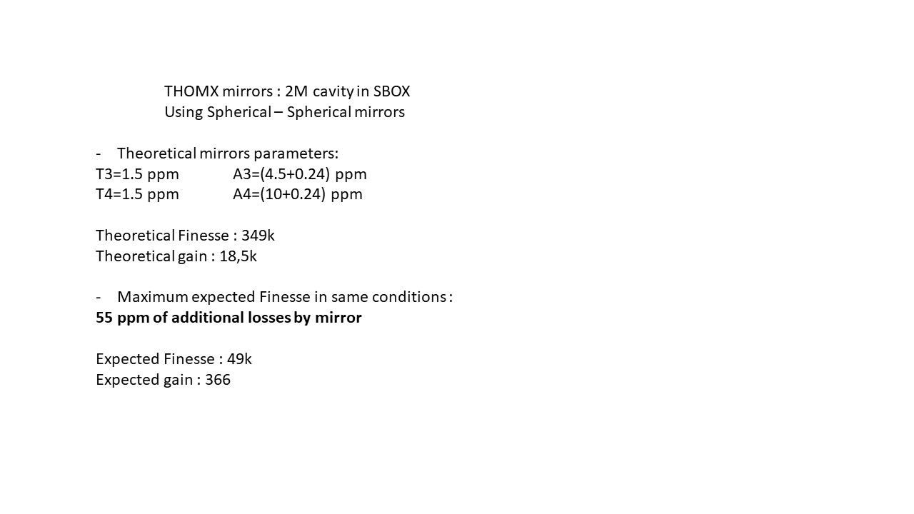
Theoretical and expected Finesse for the 2 mirror setup with the losses is calculated by Ronic for comparison between four and 2 mirror setup.
| Manar Amer wrote: |
|
The SBox cavity setup was changed to have only 2 mirrors M1 plane and M2 spherical, both from ThomX
Distance between the mirror ~ 72 cm , increased from 70 cm to take into account the thickness of the ThomX mirrors
Two lenses (300 mm @ 50 cm , 200 @ 104 cm) were placed to have the beam radius ~ 0.55 mm.
The cavity was locked with a coupling of 60 %, for Finesse measurement the sweep was taken over 100 KHz of 2 seconds.
FSR ~ 210.00 MHz, line width ~ 8.56 KHz, Finesse ~ 24 500 .
|
|
|
|
|
| Attachment 1: Screenshot_2022-07-11_1_204143.png
|
 |
| Attachment 2: Screenshot_2022-07-11_0_203646.png
|
 |
|
111
|
Tue Jul 12 10:07:05 2022 |
Manar Amer | Fixed | report | lasers and optics | detectors and electronics | Optical room | FSR change & Finesse Measurements |
The FSR of the 2 mirror (plan-spherical) Cavity was adjusted from 210 MHz to reach 216.643 MHz
it was done by having two reference irises, one at the injection point and one at the reflection
then changing the position of injection plan mirror to slightly closer distance and monitoring the reflection on the oscilloscope to be max.
The cavity modes were still seen, and we had to only improve the injection alignment after.
Me and Ronic locked in air and measured the Finesse, which was bigger by ~ 20%
average Finesse = 30208.53614
FWHM (KHz) = 7.0179
Finesse = 30869.9522
FWHM (KHz) = 7.1257
Finesse = 30403.005
FWHM (KHz) = 7.1287
Finesse = 30390.4014
FWHM (KHz) = 7.2884
Finesse = 29724.5531
FWHM (KHz) = 7.3055
Finesse = 29654.769
| Manar Amer wrote: |
|
Update for Finesse measurement, The cavity was put under vacuum ~ 1.1*10^-1 mbar
and the alignment and coupling improved.
FSR = 210.1 MHz
Average Finesse = 25686.46222
FWHM (KHz) = 8.2387
Finesse = 25501.5659
FWHM (KHz) = 8.2028
Finesse = 25613.2858
FWHM (KHz) = 8.0978
Finesse = 25945.3289
FWHM (KHz) = 8.1744
Finesse = 25702.3142
FWHM (KHz) = 8.1847
Finesse = 25669.8163
Concluded from Ronic's calculations, this could be the maximum finesse we might be able to obtain with this setup
with Gain ~ 8000
On Monday we adjust the frequency to match 2160.66 MHz and lock the Pulsed,
at the same time start we start with the CELIA amplifier.
| Manar Amer wrote: |
|
The cavity was realigned using irises instead of pinholes, gave a better alignment.
The inside of the box, the spherical and the injection mirror were cleaned and placed back inside the box.
we see beating of fundamental mode, previously at the transmission point we placed a wedge to split the beam which resulted in an elliptical mode
we removed it and placed a very thin beam splitter, the beam is circular now.
The cavity was locked in air at a coupling of ~ 60-70 %
Finesse and line width measured five readings with a Finesse average 25095.08884 of a Gain ~ 8000
FWHM (KHz) = 8.2928
Finesse = 25323.0544
FWHM (KHz) = 7.9202
Finesse = 26514.4395
FWHM (KHz) = 8.5834
Finesse = 24465.8636
FWHM (KHz) = 8.4571
Finesse = 24831.2419
FWHM (KHz) = 8.6275
Finesse = 24340.8448
Theoretical and expected Finesse for the 2 mirror setup with the losses is calculated by Ronic for comparison between four and 2 mirror setup.
| Manar Amer wrote: |
|
The SBox cavity setup was changed to have only 2 mirrors M1 plane and M2 spherical, both from ThomX
Distance between the mirror ~ 72 cm , increased from 70 cm to take into account the thickness of the ThomX mirrors
Two lenses (300 mm @ 50 cm , 200 @ 104 cm) were placed to have the beam radius ~ 0.55 mm.
The cavity was locked with a coupling of 60 %, for Finesse measurement the sweep was taken over 100 KHz of 2 seconds.
FSR ~ 210.00 MHz, line width ~ 8.56 KHz, Finesse ~ 24 500 .
|
|
|
|
| Attachment 1: 00mode.jpg
|
 |
| Attachment 2: 00mode_diameter.jpg
|
 |
| Attachment 3: 00mode_diameter_fit.jpg
|
 |
|
110
|
Fri Jul 8 19:37:24 2022 |
Manar Amer | Fixed | report | lasers and optics | detectors and electronics | Optical room | 2 Mirror Setup @ 216.6 MHz |
Update for Finesse measurement, The cavity was put under vacuum ~ 1.1*10^-1 mbar
and the alignment and coupling improved.
FSR = 210.1 MHz
Average Finesse = 25686.46222
FWHM (KHz) = 8.2387
Finesse = 25501.5659
FWHM (KHz) = 8.2028
Finesse = 25613.2858
FWHM (KHz) = 8.0978
Finesse = 25945.3289
FWHM (KHz) = 8.1744
Finesse = 25702.3142
FWHM (KHz) = 8.1847
Finesse = 25669.8163
Concluded from Ronic's calculations, this could be the maximum finesse we might be able to obtain with this setup
with Gain ~ 8000
On Monday we adjust the frequency to match 2160.66 MHz and lock the Pulsed,
at the same time start we start with the CELIA amplifier.
| Manar Amer wrote: |
|
The cavity was realigned using irises instead of pinholes, gave a better alignment.
The inside of the box, the spherical and the injection mirror were cleaned and placed back inside the box.
we see beating of fundamental mode, previously at the transmission point we placed a wedge to split the beam which resulted in an elliptical mode
we removed it and placed a very thin beam splitter, the beam is circular now.
The cavity was locked in air at a coupling of ~ 60-70 %
Finesse and line width measured five readings with a Finesse average 25095.08884 of a Gain ~ 8000
FWHM (KHz) = 8.2928
Finesse = 25323.0544
FWHM (KHz) = 7.9202
Finesse = 26514.4395
FWHM (KHz) = 8.5834
Finesse = 24465.8636
FWHM (KHz) = 8.4571
Finesse = 24831.2419
FWHM (KHz) = 8.6275
Finesse = 24340.8448
Theoretical and expected Finesse for the 2 mirror setup with the losses is calculated by Ronic for comparison between four and 2 mirror setup.
| Manar Amer wrote: |
|
The SBox cavity setup was changed to have only 2 mirrors M1 plane and M2 spherical, both from ThomX
Distance between the mirror ~ 72 cm , increased from 70 cm to take into account the thickness of the ThomX mirrors
Two lenses (300 mm @ 50 cm , 200 @ 104 cm) were placed to have the beam radius ~ 0.55 mm.
The cavity was locked with a coupling of 60 %, for Finesse measurement the sweep was taken over 100 KHz of 2 seconds.
FSR ~ 210.00 MHz, line width ~ 8.56 KHz, Finesse ~ 24 500 .
|
|
|
| Attachment 1: Screenshot_2022-07-08_2_182405.png
|
 |
|
109
|
Fri Jul 8 17:48:48 2022 |
Manar Amer | Fixed | report | lasers and optics | detectors and electronics | Optical room | 2 Mirror Setup @ 216.6 MHz |
The cavity was realigned using irises instead of pinholes, gave a better alignment.
The inside of the box, the spherical and the injection mirror were cleaned and placed back inside the box.
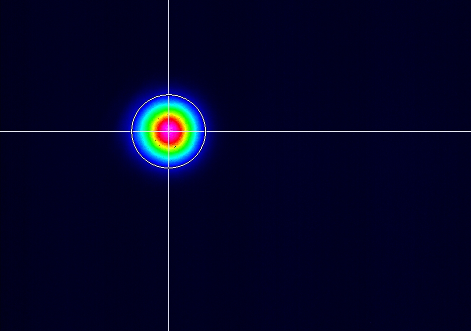
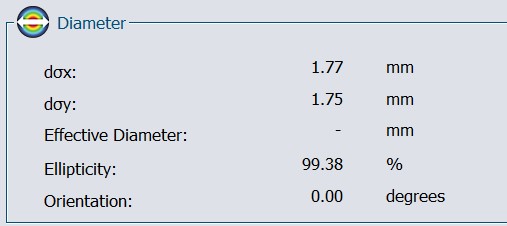
we see beating of fundamental mode, previously at the transmission point we placed a wedge to split the beam which resulted in an elliptical mode
we removed it and placed a very thin beam splitter, the beam is circular now.
The cavity was locked in air at a coupling of ~ 60-70 %
Finesse and line width measured five readings with a Finesse average 25095.08884 of a Gain ~ 8000
FWHM (KHz) = 8.2928
Finesse = 25323.0544
FWHM (KHz) = 7.9202
Finesse = 26514.4395
FWHM (KHz) = 8.5834
Finesse = 24465.8636
FWHM (KHz) = 8.4571
Finesse = 24831.2419
FWHM (KHz) = 8.6275
Finesse = 24340.8448
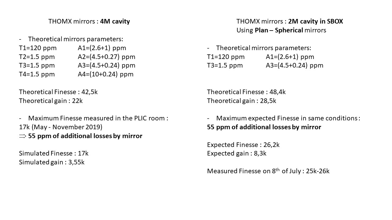
Theoretical and expected Finesse for the 2 mirror setup with the losses is calculated by Ronic for comparison between four and 2 mirror setup.
| Manar Amer wrote: |
|
The SBox cavity setup was changed to have only 2 mirrors M1 plane and M2 spherical, both from ThomX
Distance between the mirror ~ 72 cm , increased from 70 cm to take into account the thickness of the ThomX mirrors
Two lenses (300 mm @ 50 cm , 200 @ 104 cm) were placed to have the beam radius ~ 0.55 mm.
The cavity was locked with a coupling of 60 %, for Finesse measurement the sweep was taken over 100 KHz of 2 seconds.
FSR ~ 210.00 MHz, line width ~ 8.56 KHz, Finesse ~ 24 500 .
|
|
| Attachment 1: 00mode.jpg
|
 |
| Attachment 2: 00mode_diameter.jpg
|
 |
| Attachment 3: Screenshot_2022-07-08_0_164115.png
|
 |
| Attachment 4: Slide1.JPG
|
 |
| Attachment 5: Slide2.JPG
|
 |
|
108
|
Fri Jul 8 17:10:44 2022 |
Manar Amer | Fixed | report | lasers and optics | Optical room | Images of ThomX mirrors |
Mirror images in the previous log showing the metal deposit of the coating of the spherical mirrors
(not sent by mail due to large size of images)
| Manar Amer wrote: |
|
Under the microscope,
the spherical mirrors show the deposit of metal dots on the reflecting surface and not on the back of the mirrors
The mirror with fewer spots near the center was used in the setup.
|
|
|
107
|
Fri Jul 8 17:09:26 2022 |
Manar Amer | Fixed | report | lasers and optics | Optical room | Images of ThomX mirrors |
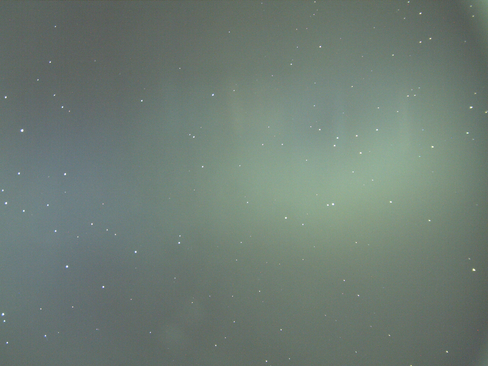
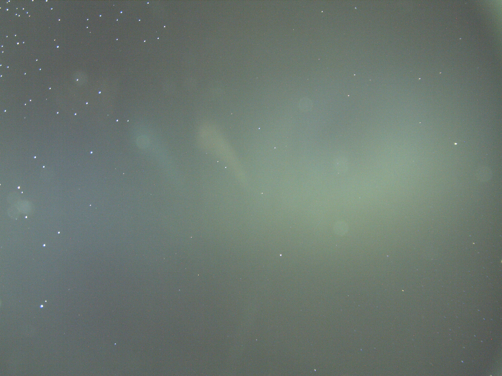
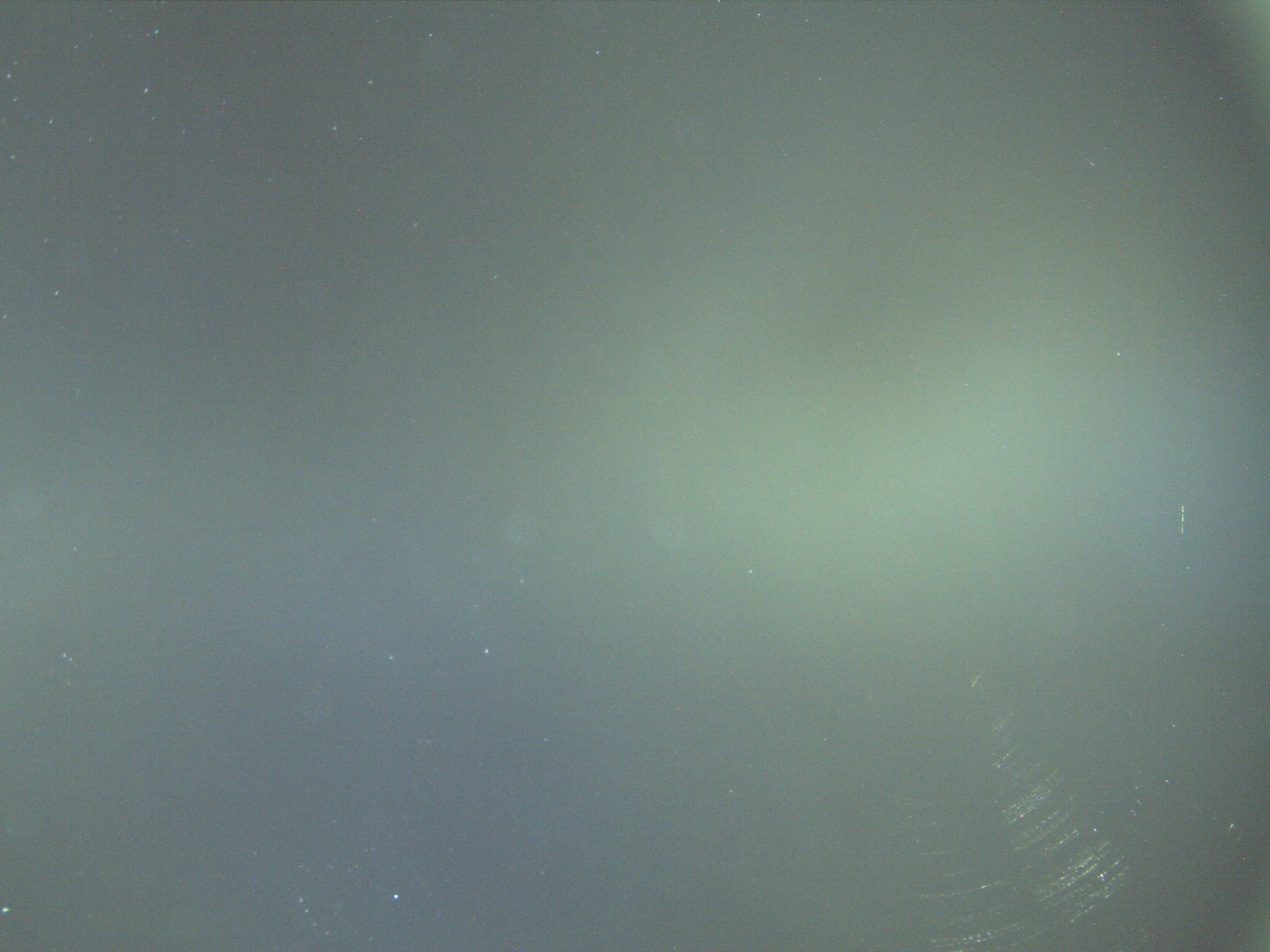
Under the microscope,
the spherical mirrors show the deposit of metal dots on the reflecting surface and not on the back of the mirrors
The mirror with fewer spots near the center was used in the setup.
|
| Attachment 1: ThomX_Spherical_Front_coating.jpg
|
 |
| Attachment 2: ThomX_Spherical_2_Front_coating.jpg
|
 |
| Attachment 3: ThomX_Spherical_back.jpg
|
 |
|
106
|
Wed Jul 6 19:57:17 2022 |
Manar Amer | Fixed | report | lasers and optics | detectors and electronics | Optical room | 2 Mirror Setup @ 216.6 MHz |
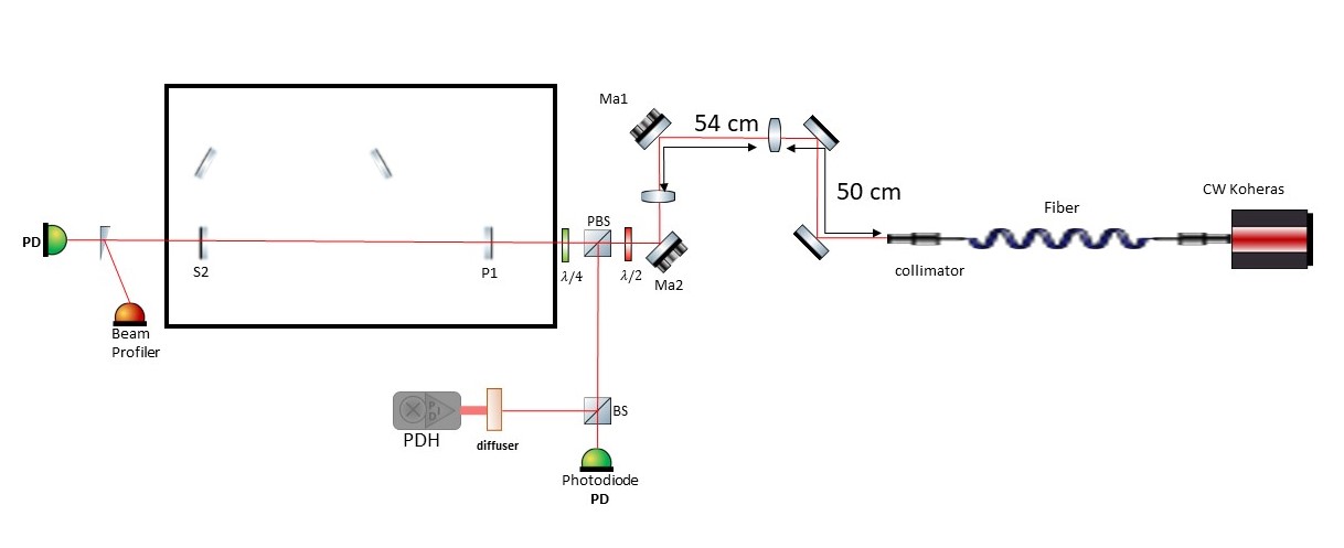
The SBox cavity setup was changed to have only 2 mirrors M1 plane and M2 spherical, both from ThomX
Distance between the mirror ~ 72 cm , increased from 70 cm to take into account the thickness of the ThomX mirrors
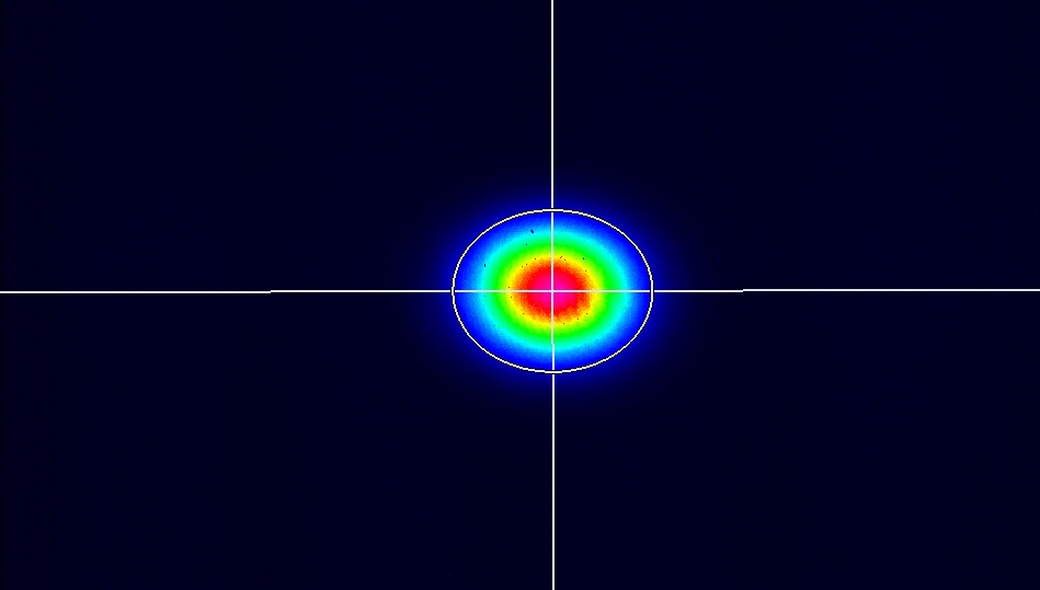
Two lenses (300 mm @ 50 cm , 200 @ 104 cm) were placed to have the beam radius ~ 0.55 mm.
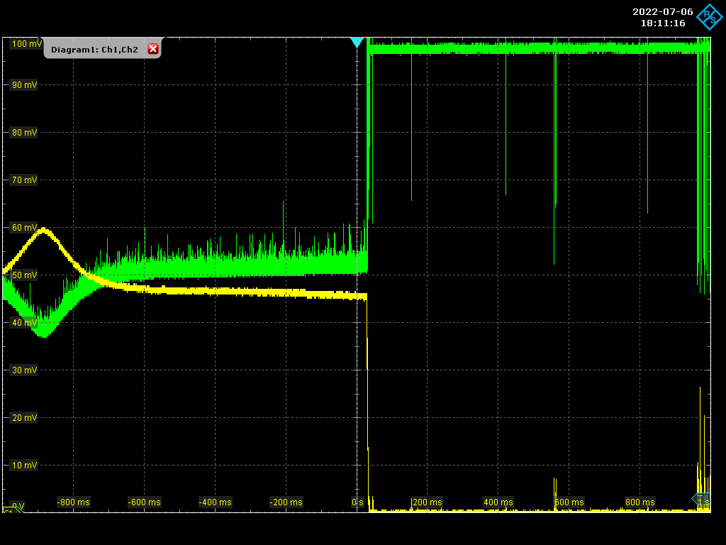
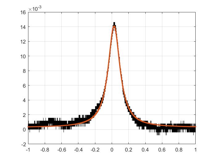
The cavity was locked with a coupling of 60 %, for Finesse measurement the sweep was taken over 100 KHz of 2 seconds.
FSR ~ 210.00 MHz, line width ~ 8.56 KHz, Finesse ~ 24 500 .
|
| Attachment 1: 20220706_Setup.jpg
|
 |
| Attachment 2: Screenshot_2022-07-06_1_181116.png
|
 |
| Attachment 3: Finesse_Fit.jpg
|
 |
| Attachment 4: 00mode.jpg
|
 |
| Attachment 5: 00mode_diameter.jpg
|
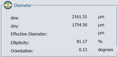 |
|
105
|
Wed Jul 6 18:39:38 2022 |
Manar Amer | Fixed | report | lasers and optics | vacuum | Optical room | SBox Finesse at 216.6625 MHz |
| Manar Amer wrote: |
|
Max Finesse obtained @ 4 mirror setup was ~ 19 300
With M1 from ThomX , M2/M3/M4 from SBox
| Manar Amer wrote: |
|
The Sbox currently has the injection from ThomX installed T ~ 120 ppm , M2 planar from Sbox spare and M3 / M4 spherical mirrors from Sbox installed.
The last finesse measurement that was done gave a Finesse of ~ 19300 (After cleaning M2 using ethanol + aceton + pure water)
on Friday the whole optical table was cleaned again and the inside of the box was cleaned (even with a lot of dust inside the box the Finesse was 19300 )
all the mirrors were cleaned after using the three steps, M3 and M4 had clear visible dust on them.
D-shaped mirrors were installed again between M1 and M2
The alignment was redone and the beating observed , There is still a need for alignment improvement.
the cavity is under vacuum ~ 4.8*10^-2 mbar on Friday evening (~ 19h00) , The cavity is yet to be locked and to measure its Finesse
A PowerPoint showing the last finesse measurement and the error signal of the menhir laser lock
|
|
|
|
104
|
Wed Jul 6 18:39:25 2022 |
Manar Amer | Fixed | report | lasers and optics | vacuum | Optical room | SBox Finesse at 216.6625 MHz |
Max Finesse obtained @ 4 mirror setup was ~ 19 300
With M1 from ThomX , M2/M3/M4 from SBox
| Manar Amer wrote: |
|
The Sbox currently has the injection from ThomX installed T ~ 120 ppm , M2 planar from Sbox spare and M3 / M4 spherical mirrors from Sbox installed.
The last finesse measurement that was done gave a Finesse of ~ 19300 (After cleaning M2 using ethanol + aceton + pure water)
on Friday the whole optical table was cleaned again and the inside of the box was cleaned (even with a lot of dust inside the box the Finesse was 19300 )
all the mirrors were cleaned after using the three steps, M3 and M4 had clear visible dust on them.
D-shaped mirrors were installed again between M1 and M2
The alignment was redone and the beating observed , There is still a need for alignment improvement.
the cavity is under vacuum ~ 4.8*10^-2 mbar on Friday evening (~ 19h00) , The cavity is yet to be locked and to measure its Finesse
A PowerPoint showing the last finesse measurement and the error signal of the menhir laser lock
|
|
|
103
|
Wed Jul 6 18:37:02 2022 |
Manar Amer | Fixed | report | lasers and optics | Optical room | Divergence of the CW beam after collimator |
Closing the series of the telescope for the beam @ 133.33 MHz
|
|
102
|
Wed Jul 6 18:35:38 2022 |
Manar Amer | Fixed | report | lasers and optics | Optical room | Fundamental Mode TEM00 |
Closing series of 00 mode for FSR @ 133.33 MHz
| Manar Amer wrote: |
|
Images of the Transmitted beam at M2 mirror at different days.
The first one was from last week, the second from yesterday.
There is misalignment (drift due to temperature) from the position where the beam was initially. ( reference taken between centers of mode and direct injected beam)
it is most clear in the vertical position.
| Manar Amer wrote: |
|
Adding images from the transmission after the spherical mirrors M3 and M4 window for a resonating mode inside the cavity.
There appears to be some misalignment from the center of the mirror ???
| Manar Amer wrote: |
|
The current setup for the SBox has a beam viewer and 2 photodiodes placed at reflection and transmission.
The CW laser piezoelectric crystal was driven using the lase lock system to observe the 00 mode.
Mode Observed and has no reflection (from what was previously seen)
higher order modes are resonating with 00 mode , example 11 mode (shown in image attached)
the coupling is yet to be seen and measured.
|
|
|
|
|
101
|
Wed Jul 6 18:34:12 2022 |
Manar Amer | Fixed | report | lasers and optics | detectors and electronics | software | Optical room | Cavity Lock |
Closing the series for the setup
The cavity was only locked @ 133.33 MHz but the Finesse was not measured
The FSR was changed to match the new laser MENHIR 216.6625 MHz
| Manar Amer wrote: |
|
Cavity locked today under vacuum and no airflow, it is stable over a long time
the alignment was improved and an increase of the transmission by 20 % from its original value
unfortunately, data from the oscilloscope was saved, but it was not in the correct format (image) to show.
Attached ; the mode shape, the new motor positions.
| Manar Amer wrote: |
|
Current setup at SBox for locking the cavity
After spacial matching, the coupling increased to ~ 15 - 20 %
The locking was done for the fundamental mode, tried to improve the coupling with the motors, but the lock is very unstable to be investigated. (Note: the cavity in under normal pressure)
| Manar Amer wrote: |
|
Start with the cavity lock images attached, taken from last week, at start we have a coupling ~ 5% and started improving on the alignment .
The image of 00 modes attached corresponds to the coupling seen on the oscilloscope.
We have a higher coupling with the 11 mode due to the size of the injected beam in comparison to mode
lenses were added to improve it.
|
|
|
|
|
100
|
Mon Jun 27 08:52:46 2022 |
Manar Amer | Fixed | report | lasers and optics | vacuum | Optical room | SBox Finesse at 216.6625 MHz |
The Sbox currently has the injection from ThomX installed T ~ 120 ppm , M2 planar from Sbox spare and M3 / M4 spherical mirrors from Sbox installed.
The last finesse measurement that was done gave a Finesse of ~ 19300 (After cleaning M2 using ethanol + aceton + pure water)
on Friday the whole optical table was cleaned again and the inside of the box was cleaned (even with a lot of dust inside the box the Finesse was 19300 )
all the mirrors were cleaned after using the three steps, M3 and M4 had clear visible dust on them.
D-shaped mirrors were installed again between M1 and M2
The alignment was redone and the beating observed , There is still a need for alignment improvement.
the cavity is under vacuum ~ 4.8*10^-2 mbar on Friday evening (~ 19h00) , The cavity is yet to be locked and to measure its Finesse
A PowerPoint showing the last finesse measurement and the error signal of the menhir laser lock
|
| Attachment 1: 20220624_SBox_MENHIR.pptx
|
|
99
|
Tue Jun 21 23:52:28 2022 |
Manar Amer | Fixed | report | mechanics | lasers and optics | detectors and electronics | Optical room | Menhir Pulsed Laser |
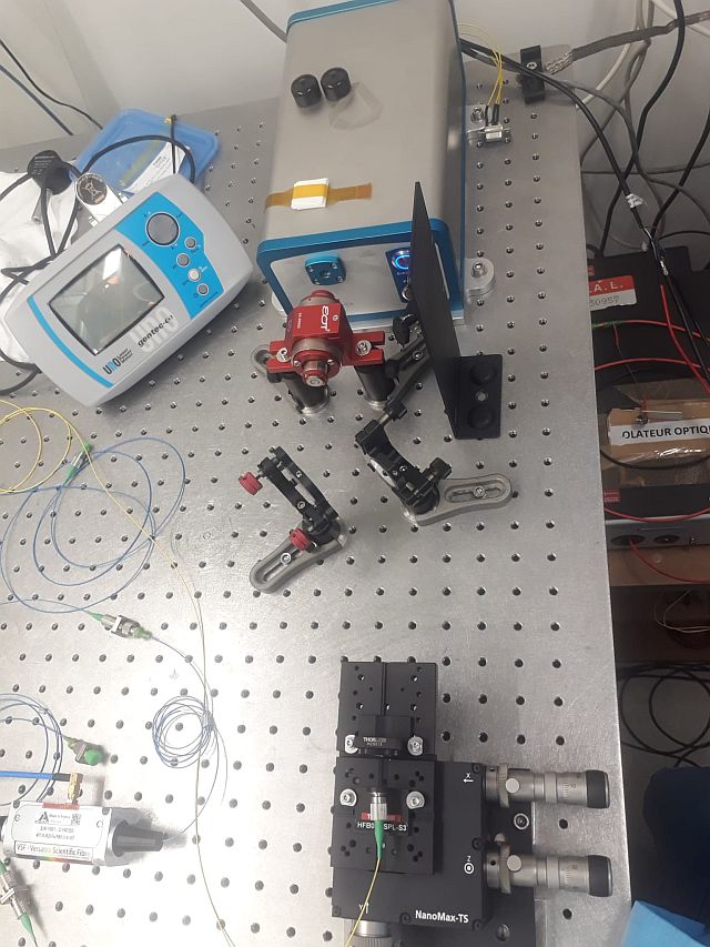
The SBox Length (FSR), was changed to match the repetition rate of the Menhir pulsed laser Frep = 216.6625 MHz
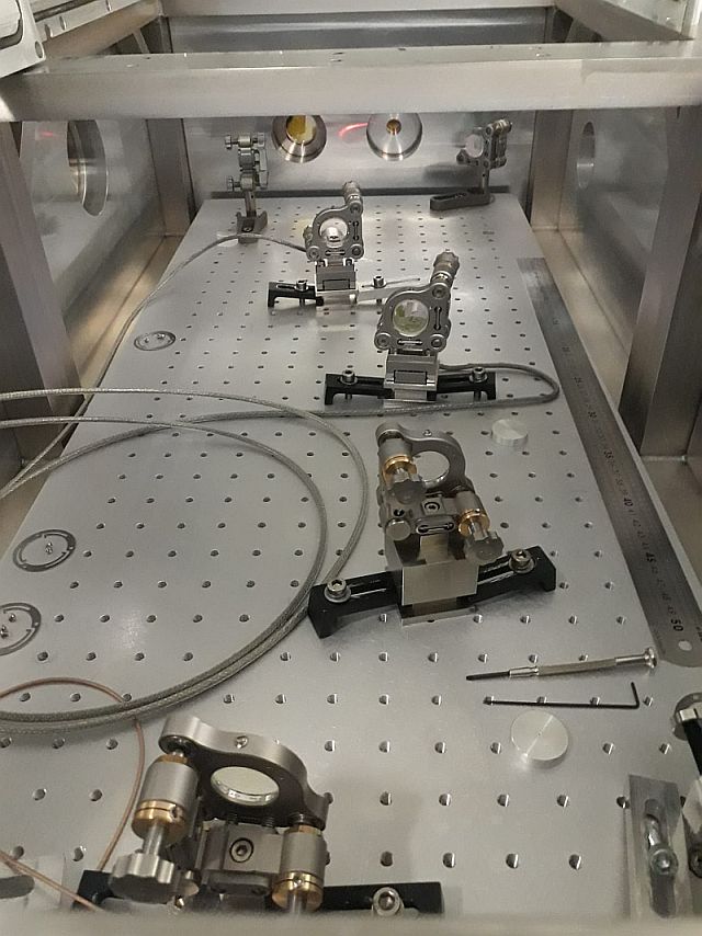
It was changed by removing the 2 D-shaped mirrors placed between M1 and M2, distance between M1-M2 ~= 169 mm
it was still needed to be adjusted with M1 motor to reach the correct FSR.
The pulsed laser is placed on the able with injection into a fiber
The Finesse of the cavity has progressed from ~2500 to ~ 18 000
** Note: PowerPoint attached shows the progress over the last two weeks on the laser and |
| Attachment 1: MENHIR_injection_into_fiber.jpg
|
 |
| Attachment 2: SBox_M.jpg
|
 |
| Attachment 3: 20220620_SBox_MENHIR.pptx
|
|
98
|
Thu Jun 9 19:59:42 2022 |
Manar Amer | Fixed | report | lasers and optics | detectors and electronics | software | Optical room | Cavity Lock |
Cavity locked today under vacuum and no airflow, it is stable over a long time
the alignment was improved and an increase of the transmission by 20 % from its original value
unfortunately, data from the oscilloscope was saved, but it was not in the correct format (image) to show.
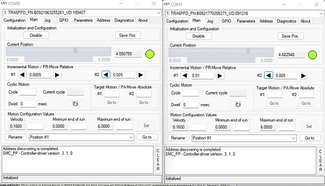
Attached ; the mode shape, the new motor positions.
| Manar Amer wrote: |
|
Current setup at SBox for locking the cavity
After spacial matching, the coupling increased to ~ 15 - 20 %
The locking was done for the fundamental mode, tried to improve the coupling with the motors, but the lock is very unstable to be investigated. (Note: the cavity in under normal pressure)
| Manar Amer wrote: |
|
Start with the cavity lock images attached, taken from last week, at start we have a coupling ~ 5% and started improving on the alignment .
The image of 00 modes attached corresponds to the coupling seen on the oscilloscope.
We have a higher coupling with the 11 mode due to the size of the injected beam in comparison to mode
lenses were added to improve it.
|
|
|
| Attachment 1: 00_Mode_Locked_Under_vacuum.bmp
|
| Attachment 2: Ma1_Ma2_Horizontal_end-of-day.jpg
|
 |
| Attachment 3: Ma1_Ma2_Vertical_end-of-day.jpg
|
 |
|
97
|
Wed Jun 8 11:31:47 2022 |
Manar Amer | Fixed | report | lasers and optics | detectors and electronics | software | Optical room | Cavity Lock |
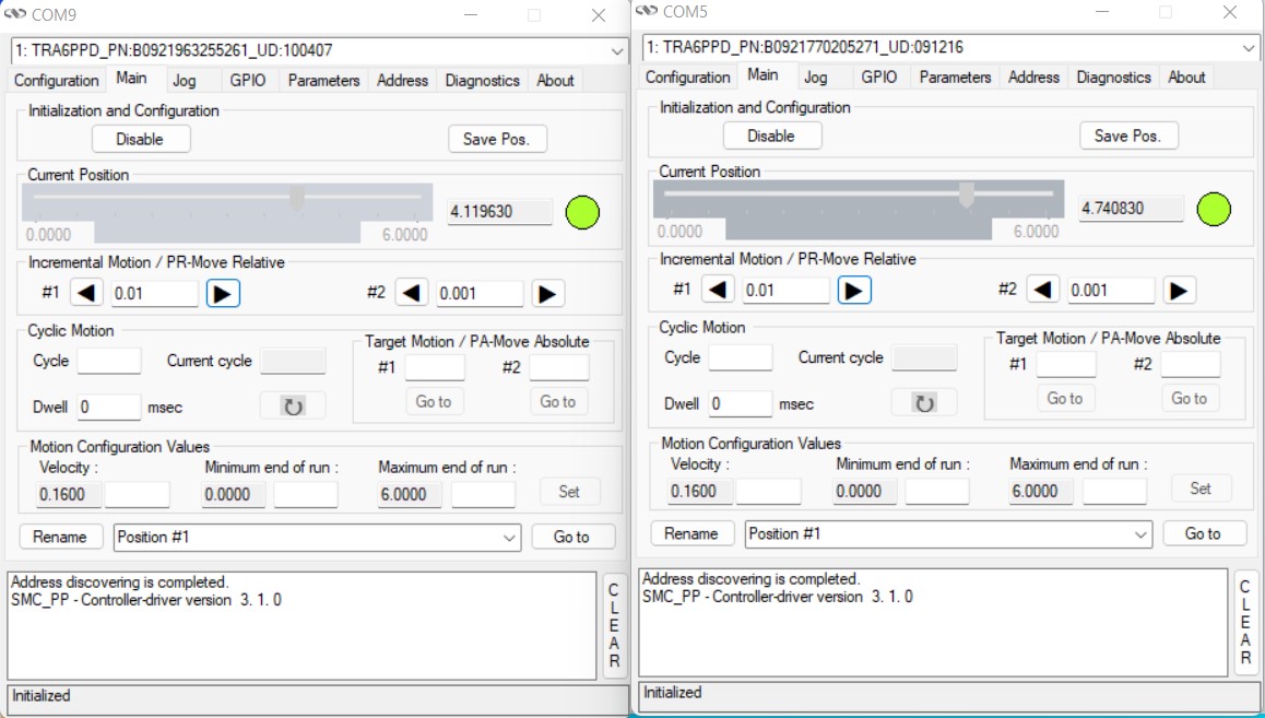
Current setup at SBox for locking the cavity
After spacial matching, the coupling increased to ~ 15 - 20 %
The locking was done for the fundamental mode, tried to improve the coupling with the motors, but the lock is very unstable to be investigated. (Note: the cavity in under normal pressure)
| Manar Amer wrote: |
|
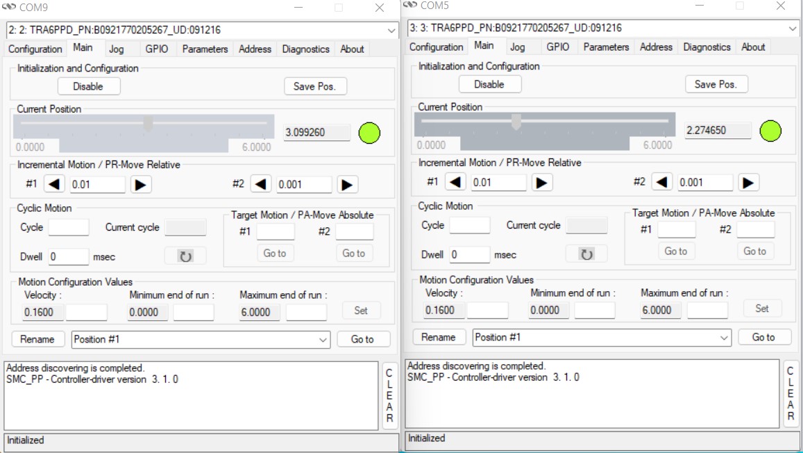
Start with the cavity lock images attached, taken from last week, at start we have a coupling ~ 5% and started improving on the alignment .
The image of 00 modes attached corresponds to the coupling seen on the oscilloscope.
We have a higher coupling with the 11 mode due to the size of the injected beam in comparison to mode
lenses were added to improve it.
|
|
| Attachment 1: 20220607_SBox_Setup.png
|
 |
| Attachment 2: Ma1_Ma2_Horizontal_end-of-day.jpg
|
 |
| Attachment 3: Ma1_Ma2_Vertical_end-of-day.jpg
|
 |
|
96
|
Wed Jun 8 11:24:35 2022 |
Manar Amer | Fixed | report | lasers and optics | Optical room | Telescope - Spacial Matching |
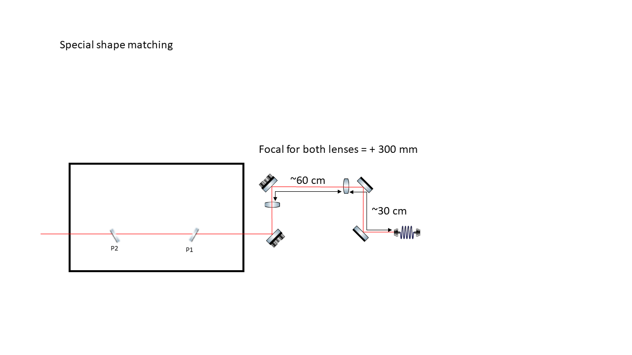
Divergence of the CW beam out of the collimator measured after 1 meter to be
- 2
 x = 0.7425 mrad --> x = 0.37125 mrad x = 0.7425 mrad --> x = 0.37125 mrad
- 2 y = 0.7115 mrad --> y = 0.3575 mrad
two lenses were placed to decrease the diameter of the injected beam |
| Attachment 1: SBox_Spacial_Matching_Telescope.png
|
 |
|
95
|
Wed Jun 8 11:10:17 2022 |
Manar Amer | Fixed | report | lasers and optics | detectors and electronics | software | Optical room | Cavity Lock |
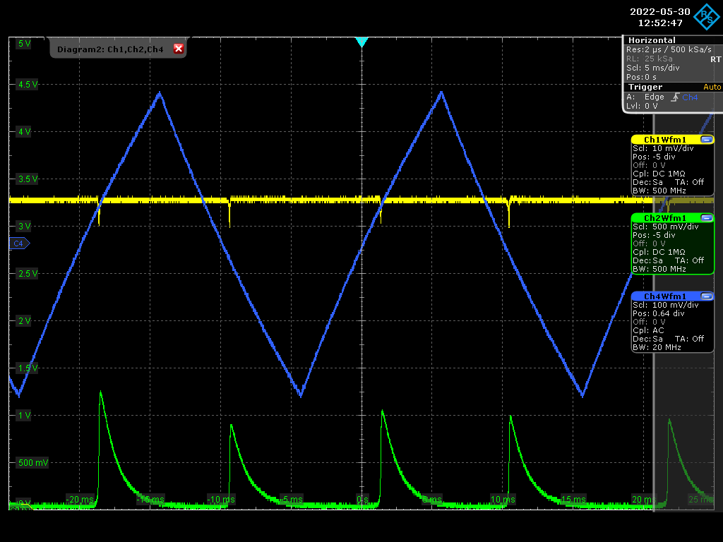
Start with the cavity lock images attached, taken from last week, at start we have a coupling ~ 5% and started improving on the alignment .
The image of 00 modes attached corresponds to the coupling seen on the oscilloscope.
We have a higher coupling with the 11 mode due to the size of the injected beam in comparison to mode
lenses were added to improve it. |
| Attachment 1: Screenshot_2022-05-30_0_125247.png
|
 |
| Attachment 2: 20220530_00_Mode.bmp
|
| Attachment 3: 11.bmp
|
|
94
|
Wed Jun 8 10:58:15 2022 |
Manar Amer | Fixed | report | lasers and optics | Optical room | Fundamental Mode TEM00 |
Images of the Transmitted beam at M2 mirror at different days.
The first one was from last week, the second from yesterday.
There is misalignment (drift due to temperature) from the position where the beam was initially. ( reference taken between centers of mode and direct injected beam)
it is most clear in the vertical position.
| Manar Amer wrote: |
|
Adding images from the transmission after the spherical mirrors M3 and M4 window for a resonating mode inside the cavity.
There appears to be some misalignment from the center of the mirror ???
| Manar Amer wrote: |
|
The current setup for the SBox has a beam viewer and 2 photodiodes placed at reflection and transmission.
The CW laser piezoelectric crystal was driven using the lase lock system to observe the 00 mode.
Mode Observed and has no reflection (from what was previously seen)
higher order modes are resonating with 00 mode , example 11 mode (shown in image attached)
the coupling is yet to be seen and measured.
|
|
|
| Attachment 1: 20220530_00_Mode.bmp
|
| Attachment 2: 00_Mode_Beam_Transmitted_Position_drift_due_to_temperature.bmp
|
|
93
|
Wed Jun 8 10:47:45 2022 |
Manar Amer | Fixed | report | lasers and optics | Optical room | SBox Alignment |
Closing Series for Alignment.
Beating observed, beam is in the locking stages
| Manar Amer wrote: |
|
The external and internal alignment was redone.
External Alignment : the collimator position moved so in order to have a good start I placed 2 metallic mirrors and did a rough retrace of it's line through the cavity box.
It helped as I did not have to do a lot of adjustment on Ma1 and Ma2 position (new position attached)
Internal Alignment: I replaced the 2 pinholes inside the cavity box with another set where the holes are more symmetric, it shows in the alignment.
Images attached of the beam diffraction pattern after each mirror pinhole.
The injection mirror was placed at the end of the alignment.
Alignment Done !!!!!!!!!!!!!
| Manar Amer wrote: |
|
M2 Sbox changed to spare. Alignment of M2 was redone.
With the help of Ronic , We observe fundamental mode of the cavity with higher order modes. A frequency scan on the piezo was done to find the beating frequency , the shape is elliptical with no clear deformation.
The beam seems to be hitting something, which causes a reflection seen on the beam profiler.
We started a slow scan to improvement of the outside alignment.
At the end of the day, I can only get the TM01 and TM10 modes,
alignment to be continued tomorrow + the scan offset
Note: observation on TM01 and TM10 modes, we clearly see that the beam position is different from the mode center position !!
| Manar Amer wrote: |
|
Yesterday, to find the source of why the mode is deformed, I tried to rotate the mirrors to see if there is a change.
I started with M2 and rotated it by ~ 90 degrees, there is a change in the shape of the beam.(image attached)
Will see if changing M2 to the spare M2 from SBox can fix the issue.
At the end of the day, alignment was lost.
will be redone today while changing M2 mirror.
| Manar Amer wrote: |
|
Today; replaced the M1 SBox mirror with M1 from gamma factory , following the previous alignment.
Removed all mirrors and cleaned them one by one.
Started with no M1, placed M2 did its alignment through M3 pinhole, then placed M3 aligned it through M4 pinhole, then placed M4 aligned it through M1 pinhole.
Placed M1 Gamma factory at the end
Note: mirror is new was not used before, took image on microscope there was no dust in the center, but there was little on the edges (cleaned it using spin-coater)
beating of fundamental mode observed (at M2 transmission) immediately with very higher order modes, slight adjustment on M4 suppressed them.
The beam is not circular and still has some deformation, M1 was changed, so it could be a damaged point at one of the other mirrors (to be investigated tomorrow)!!
No significant damage seen on the other mirrors.
|
Manar Amer wrote:
|
|
Last week In FP cavity we had all SBox mirrors including the damaged M1 mirror.
The beating was observed with just a slight adjustment on M4 alignment.
In addition, it was also observed while driving the piezo of the CW laser.
In the attached image of the beam at transmission point at M2 mirror, the shape of the beam is deformed.
one of the factors could be related to the damaged spot on M1 mirror. The deformation position can also be seen in the higher order modes.
after changing the injection mirror to Gamma factory M1, this deformation should disappear.
| Manar Amer wrote: |
|
Finished the alignment of the SBox with M1 of SBox placed, to be changed to gamma factory mirror later
Observed what seems to be transmission through M2 mirror, to be confirmed. image attached shows it
a PowerPoint attached showing the details of today's work.
| Manar Amer wrote: |
- Adjust the placement of the Irises (done at the start of the day, adjusted at the end when M1 mirror was placed)
- Improvement on the Ma1 and Ma2 (The Alignment Mirrors)
- Improves the alignment a bit. There is an observation where there is no symmetry in the image, concluded to be because of the pinholes that are usually used for the alignment the circle cut is not symmetric (took images on phone of pinholes)
- This explains why, for the pinhole used on M1, we see a little more symmetry than the pinhole used on M2.
-
- Placed M1 mirror from Sbox (with damage spot in the middle), after cleaning it using the spincoater, only used to adjust the injection into the mirror where it will give Horizontal displacement due to the thickness of the mirror.
- Last position of the motors attached
- Installed the 2 dielectric mirrors for the reflection line
- Did a rough alignment for the reflection line to have it exit through the reflection window.
Note about mirrors : They were cleaned a year a go and placed in the boxes. When opened the box and seen under microscope they were very dirty with dust particle
Specially from the back, I believe the boxes have dust in them (to be verified under the UV light / Microscope !!!!!!!! )
| Manar Amer wrote: |
|
Remember to update the position of the reference Irises tomorrow !!!!
| Manar Amer wrote: |
|
After pointers and Advice from Aurélien,
improvement of the beam alignment through M1 and M2 irises was done.
To improve the image on the beam profiler, I cleaned the alignment mirrors and the windows using pure ethanol and optical lens cleaning tissue,
a significant improvement after cleaning the inside of M2 Window. Images have less dust diffraction rings.
Attached new images of the beam:
- New Ma1 and Ma2 motor position
- After M1 pinhole optimized (saturated)
- After M2 and M1 pinhole optimizing (saturated and not)
| Manar Amer wrote: |
|
SBox alignment, using CW laser Koheras power 1 mW
- Finished M1 and M2 alignment using the diffraction patterns seen on the beam profiler, the beam fit is not very good ?? (image taken)
- Positions of Ma1 and Ma2 motors are registered (image taken)
- Placed Fixed 2 irises at M1 window and M2 window (Image taken while both are closed)
- Distance between the collimator and beam profiler ~ 2 m
- Distance between collimator and M1 diaphragm ~ 1 m
- Distance between collimator and M2 diaphragm ~ 1.6 m
| Manar Amer wrote: |
|
Starting with the alignment of the KBox using CW Koheras.
The size of the CW output from the collimator at 1 meter from is ~ 2.4 mm, to be adjusted with lenses to match the cavity !!! (attached image)
For the 2 alignment mirrors, I am only able to control 3 axes for now (motor issue for the fourth to be fixed !!) , Horizontal and vertical for Ma1 and Horizontal for Ma2(closes to injection window).
Started with only irises placed on both the M1 and M2. Placed a beam profiler at the window behind M2 to observe an output beam.
Motors position for the 3 axes and beam shape and position after M2 attached.
|
|
|
|
|
|
|
|
|
|
|
|