| ID |
Date |
Author |
Status |
Type |
Category |
Location |
Title |
|
152
|
Fri Sep 9 12:45:19 2022 |
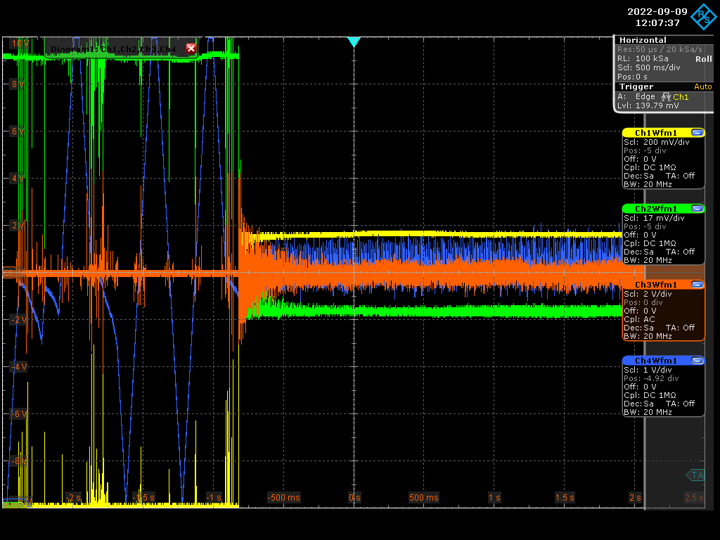
Manar Amer | Fixed | report | lasers and optics | Optical room | Locking Amplifier with Cavity |
image of the lock with Coupling of ~ 60%
| Manar Amer wrote: |
|
We locked the cavity, and it is stable using the Transmission,
the high frequency that we thought could have a reason for instability, is due to the high power on the photo diode of the PDH box which can cause non-linearity effects in the signal.
We also closed the fan of the third stage and there was no significant change on the error signal and the piezo+AOM compensation signal.
| Manar Amer wrote: |
|
We managed to lock the cavity by adding the AOM , but the lock is still difficult to stabilize.
There is some high frequency compensated by the AOM at ~ 170 kHz (yet to understand from where it comes from)
| Manar Amer wrote: |
|
We played on the CEP using the USB command "id0=xxxxx" of the Menhir.
we put id0=48650 and we improved A LOT the transmission and coupling (~ 60%)
here is an image of the first attempts to lock... but the locking is quite difficult.
yellow : transmission
green : reflection
amplifier is still with 2nd stage only (Pout=~1W)
we are adding an AOM in the loop...
| Manar Amer wrote: |
|
Today, we played on the CEP but using the I-tune input of the Menhir Laser (+/- 5V maximal range).
unfortunately, one only saw a very weak improvement of the transmission by 10-20%... and the coupling improvement is almost zero.
the best improvement was for the maximal I-tune range (+5V) which maybe means that we could improve more the effect if were able to get a full range of 2pi for the CEP (instead of the present pi/2 range).
| Manar Amer wrote: |
|
Today we managed to observe the fundamental mode and stabilize the scan on it until we improved the alignment enough.
We see some coupling, but it is very week < 5% , We improved the alignment and the polarization, but there is still no explanation to why it is very low.
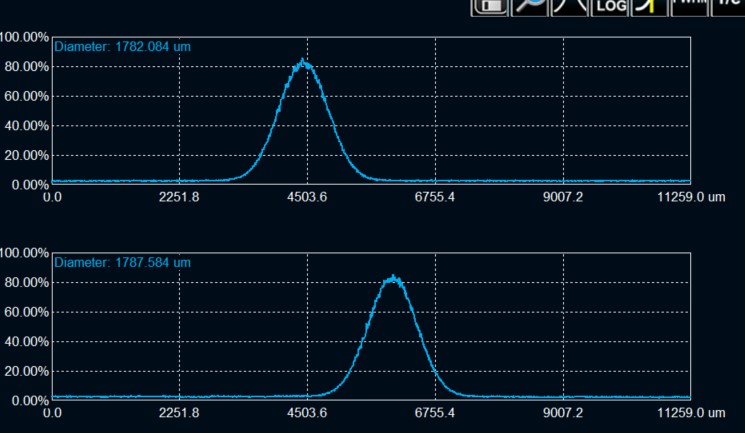
The mode shape is circular with radius = 0.89 mm at transmission point, ~ 40 cm from circular mirror.
One EOM was installed along the injection into the amplifier, we saw a drop in the power measured by the first stage monitor from ~ 8.2 mW to 7.2 mW
we improved the injection up to 7.6 mW, but it still fluctuates a lot. We need to be careful about it.
The error signal looks clean, but it is very week which is due to the weak coupling.
|
|
|
|
|
|
| Attachment 1: Screenshot_2022-09-09_0_120737.png
|
 |
|
151
|
Fri Sep 9 11:50:17 2022 |
Manar Amer | Fixed | report | lasers and optics | Optical room | Locking Amplifier with Cavity |
We locked the cavity, and it is stable using the Transmission,
the high frequency that we thought could have a reason for instability, is due to the high power on the photo diode of the PDH box which can cause non-linearity effects in the signal.
We also closed the fan of the third stage and there was no significant change on the error signal and the piezo+AOM compensation signal.
| Manar Amer wrote: |
|
We managed to lock the cavity by adding the AOM , but the lock is still difficult to stabilize.
There is some high frequency compensated by the AOM at ~ 170 kHz (yet to understand from where it comes from)
| Manar Amer wrote: |
|
We played on the CEP using the USB command "id0=xxxxx" of the Menhir.
we put id0=48650 and we improved A LOT the transmission and coupling (~ 60%)
here is an image of the first attempts to lock... but the locking is quite difficult.
yellow : transmission
green : reflection
amplifier is still with 2nd stage only (Pout=~1W)
we are adding an AOM in the loop...
| Manar Amer wrote: |
|
Today, we played on the CEP but using the I-tune input of the Menhir Laser (+/- 5V maximal range).
unfortunately, one only saw a very weak improvement of the transmission by 10-20%... and the coupling improvement is almost zero.
the best improvement was for the maximal I-tune range (+5V) which maybe means that we could improve more the effect if were able to get a full range of 2pi for the CEP (instead of the present pi/2 range).
| Manar Amer wrote: |
|
Today we managed to observe the fundamental mode and stabilize the scan on it until we improved the alignment enough.
We see some coupling, but it is very week < 5% , We improved the alignment and the polarization, but there is still no explanation to why it is very low.
The mode shape is circular with radius = 0.89 mm at transmission point, ~ 40 cm from circular mirror.
One EOM was installed along the injection into the amplifier, we saw a drop in the power measured by the first stage monitor from ~ 8.2 mW to 7.2 mW
we improved the injection up to 7.6 mW, but it still fluctuates a lot. We need to be careful about it.
The error signal looks clean, but it is very week which is due to the weak coupling.
|
|
|
|
|
|
150
|
Thu Sep 8 18:28:51 2022 |
Manar Amer | Fixed | report | lasers and optics | Optical room | Locking Amplifier with Cavity |
We wanted to increase the power of the amplifier to measure the transmission output at M2,
but locking the cavity again was very, very difficult.
We will try again tomorrow.
| Manar Amer wrote: |
|
We managed to lock the cavity by adding the AOM , but the lock is still difficult to stabilize.
There is some high frequency compensated by the AOM at ~ 170 kHz (yet to understand from where it comes from)
| Manar Amer wrote: |
|
We played on the CEP using the USB command "id0=xxxxx" of the Menhir.
we put id0=48650 and we improved A LOT the transmission and coupling (~ 60%)
here is an image of the first attempts to lock... but the locking is quite difficult.
yellow : transmission
green : reflection
amplifier is still with 2nd stage only (Pout=~1W)
we are adding an AOM in the loop...
| Manar Amer wrote: |
|
Today, we played on the CEP but using the I-tune input of the Menhir Laser (+/- 5V maximal range).
unfortunately, one only saw a very weak improvement of the transmission by 10-20%... and the coupling improvement is almost zero.
the best improvement was for the maximal I-tune range (+5V) which maybe means that we could improve more the effect if were able to get a full range of 2pi for the CEP (instead of the present pi/2 range).
| Manar Amer wrote: |
|
Today we managed to observe the fundamental mode and stabilize the scan on it until we improved the alignment enough.
We see some coupling, but it is very week < 5% , We improved the alignment and the polarization, but there is still no explanation to why it is very low.
The mode shape is circular with radius = 0.89 mm at transmission point, ~ 40 cm from circular mirror.
One EOM was installed along the injection into the amplifier, we saw a drop in the power measured by the first stage monitor from ~ 8.2 mW to 7.2 mW
we improved the injection up to 7.6 mW, but it still fluctuates a lot. We need to be careful about it.
The error signal looks clean, but it is very week which is due to the weak coupling.
|
|
|
|
|
|
149
|
Thu Sep 8 14:58:51 2022 |
Manar Amer | Fixed | report | lasers and optics | Optical room | Locking Amplifier with Cavity |
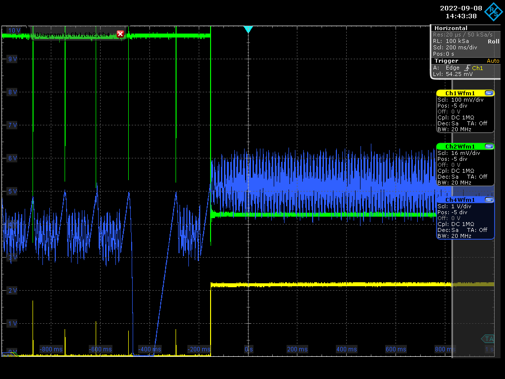
We managed to lock the cavity by adding the AOM , but the lock is still difficult to stabilize.
There is some high frequency compensated by the AOM at ~ 170 kHz (yet to understand from where it comes from)
| Manar Amer wrote: |
|
We played on the CEP using the USB command "id0=xxxxx" of the Menhir.
we put id0=48650 and we improved A LOT the transmission and coupling (~ 60%)
here is an image of the first attempts to lock... but the locking is quite difficult.
yellow : transmission
green : reflection
amplifier is still with 2nd stage only (Pout=~1W)
we are adding an AOM in the loop...
| Manar Amer wrote: |
|
Today, we played on the CEP but using the I-tune input of the Menhir Laser (+/- 5V maximal range).
unfortunately, one only saw a very weak improvement of the transmission by 10-20%... and the coupling improvement is almost zero.
the best improvement was for the maximal I-tune range (+5V) which maybe means that we could improve more the effect if were able to get a full range of 2pi for the CEP (instead of the present pi/2 range).
| Manar Amer wrote: |
|
Today we managed to observe the fundamental mode and stabilize the scan on it until we improved the alignment enough.
We see some coupling, but it is very week < 5% , We improved the alignment and the polarization, but there is still no explanation to why it is very low.
The mode shape is circular with radius = 0.89 mm at transmission point, ~ 40 cm from circular mirror.
One EOM was installed along the injection into the amplifier, we saw a drop in the power measured by the first stage monitor from ~ 8.2 mW to 7.2 mW
we improved the injection up to 7.6 mW, but it still fluctuates a lot. We need to be careful about it.
The error signal looks clean, but it is very week which is due to the weak coupling.
|
|
|
|
| Attachment 1: Screenshot_2022-09-08_2_144338.png
|
 |
|
148
|
Thu Sep 8 13:39:03 2022 |
Manar Amer | Fixed | report | lasers and optics | Optical room | Locking Amplifier with Cavity |
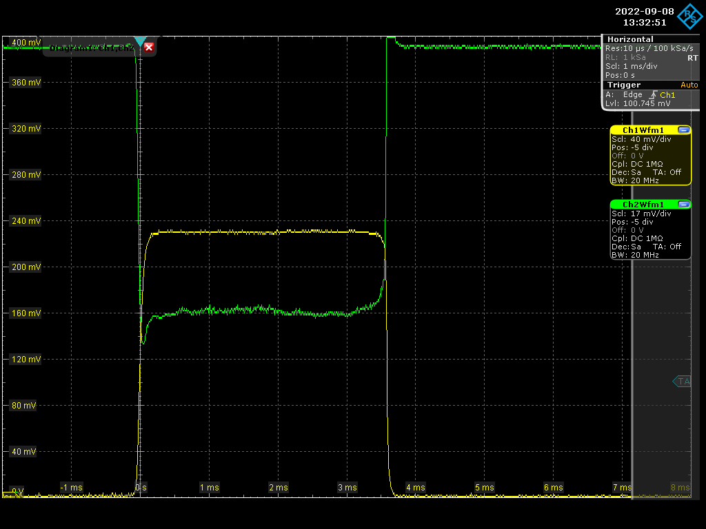
We played on the CEP using the USB command "id0=xxxxx" of the Menhir.
we put id0=48650 and we improved A LOT the transmission and coupling (~ 60%)
here is an image of the first attempts to lock... but the locking is quite difficult.
yellow : transmission
green : reflection
amplifier is still with 2nd stage only (Pout=~1W)
we are adding an AOM in the loop...
| Manar Amer wrote: |
|
Today, we played on the CEP but using the I-tune input of the Menhir Laser (+/- 5V maximal range).
unfortunately, one only saw a very weak improvement of the transmission by 10-20%... and the coupling improvement is almost zero.
the best improvement was for the maximal I-tune range (+5V) which maybe means that we could improve more the effect if were able to get a full range of 2pi for the CEP (instead of the present pi/2 range).
| Manar Amer wrote: |
|
Today we managed to observe the fundamental mode and stabilize the scan on it until we improved the alignment enough.
We see some coupling, but it is very week < 5% , We improved the alignment and the polarization, but there is still no explanation to why it is very low.
The mode shape is circular with radius = 0.89 mm at transmission point, ~ 40 cm from circular mirror.
One EOM was installed along the injection into the amplifier, we saw a drop in the power measured by the first stage monitor from ~ 8.2 mW to 7.2 mW
we improved the injection up to 7.6 mW, but it still fluctuates a lot. We need to be careful about it.
The error signal looks clean, but it is very week which is due to the weak coupling.
|
|
|
| Attachment 1: Screenshot_2022-09-08_0_133245.png
|
 |
|
147
|
Thu Sep 8 11:16:40 2022 |
Manar Amer | Fixed | report | lasers and optics | Optical room | Locking Amplifier with Cavity |
Today, we played on the CEP but using the I-tune input of the Menhir Laser (+/- 5V maximal range).
unfortunately, one only saw a very weak improvement of the transmission by 10-20%... and the coupling improvement is almost zero.
the best improvement was for the maximal I-tune range (+5V) which maybe means that we could improve more the effect if were able to get a full range of 2pi for the CEP (instead of the present pi/2 range).
| Manar Amer wrote: |
|
Today we managed to observe the fundamental mode and stabilize the scan on it until we improved the alignment enough.
We see some coupling, but it is very week < 5% , We improved the alignment and the polarization, but there is still no explanation to why it is very low.
The mode shape is circular with radius = 0.89 mm at transmission point, ~ 40 cm from circular mirror.
One EOM was installed along the injection into the amplifier, we saw a drop in the power measured by the first stage monitor from ~ 8.2 mW to 7.2 mW
we improved the injection up to 7.6 mW, but it still fluctuates a lot. We need to be careful about it.
The error signal looks clean, but it is very week which is due to the weak coupling.
|
|
|
146
|
Wed Sep 7 18:58:03 2022 |
Manar Amer | Fixed | report | lasers and optics | Optical room | Locking Amplifier with Cavity |
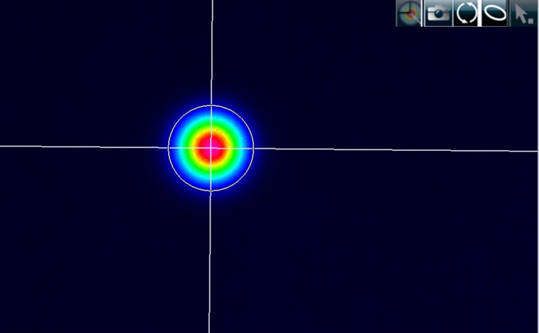
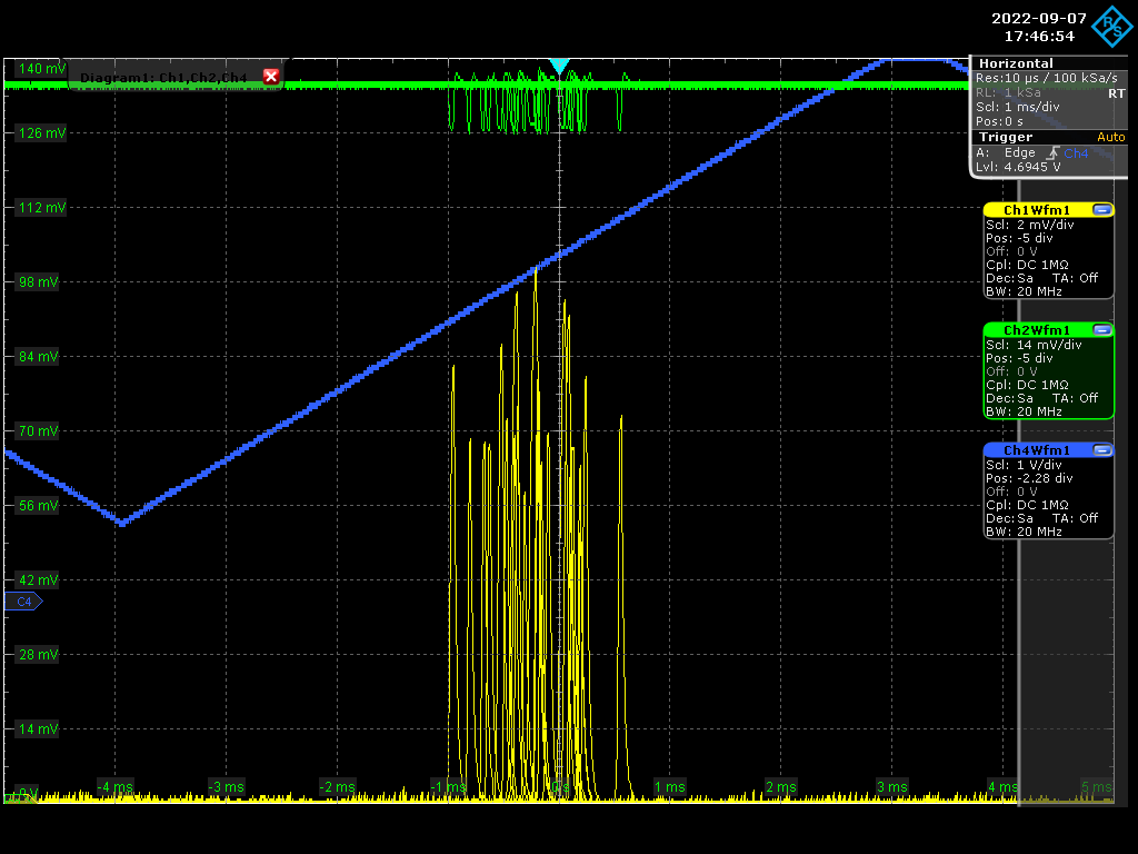
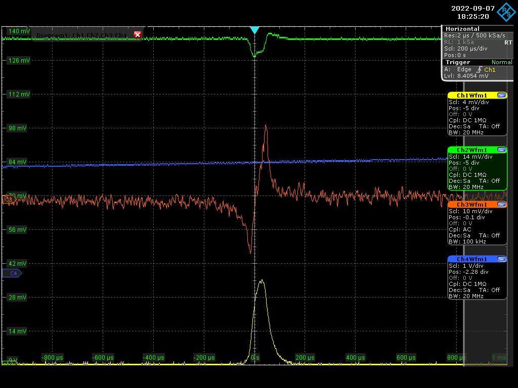
Today we managed to observe the fundamental mode and stabilize the scan on it until we improved the alignment enough.
We see some coupling, but it is very week < 5% , We improved the alignment and the polarization, but there is still no explanation to why it is very low.
The mode shape is circular with radius = 0.89 mm at transmission point, ~ 40 cm from circular mirror.
One EOM was installed along the injection into the amplifier, we saw a drop in the power measured by the first stage monitor from ~ 8.2 mW to 7.2 mW
we improved the injection up to 7.6 mW, but it still fluctuates a lot. We need to be careful about it.
The error signal looks clean, but it is very week which is due to the weak coupling.
|
| Attachment 1: 20220907_00mode.jpg
|
 |
| Attachment 2: 20220907_00mode_diameter.jpg
|
 |
| Attachment 3: Screenshot_2022-09-07_0_174654.png
|
 |
| Attachment 4: Screenshot_2022-09-07_2_182520.png
|
 |
|
145
|
Wed Sep 7 18:57:20 2022 |
Manar Amer | Fixed | report | lasers and optics | Optical room | Telescope / amplifier output |
We increased the power of the amplifier up to 10 W to see if there is a change in the beam shape at the injection point or the transmission.
There was no change in the shape of both of them from the reading at 1 W (with only the 2nd stage on)
Only saw an increase in the transmission power, which is expected.
| Manar Amer wrote: |
|
Am adjustment on the lenses position to have a smaller waist.
+ 250 mm @ 88 cm from amplifier
-150 mm @ 111 cm from amplifier
the overlap with this placement is ~ 91%
the measured beam FWHM at the injection point M1 estimated to be ~ 0.94 mm
waist = 0.85*0.94 = 0.79 mm , it is still much larger than the needed 0.58 mm radius waist.
There is an improvement in reducing higher order modes, but the fundamental is still too weak to see, we observe higher order even modes 11 , 44 , ...
| Manar Amer wrote: |
|
Note the correct beam divergence is approximately ~ 2.3 mrad
M2 = 1.1 in this fit, but it is not yet optimized !!!!! could be reason for not accurate telescope reading.
Have tInstalled a new telescope with lenses
250 mm @ 86.8 cm from amplifier ,
-150 mm @109 cm (~ 22 cm between lenses)
the beam waist measured at a point on the reflection which is relatively the same distance to the injection mirror and the beam was much smaller than before
@ ~ 2 meters from amplifier + telescope , FWHM = 1.2 mm , waist = 0.85 * FWHM = 1.02 mm
| Manar Amer wrote: |
|
Here is a view of beam propagation in the optical software : GaussianBeam
the red filled shape is the model of the CELIA amplifier beam propagation with a divergence of 4.46 mrad
(the 2 black dots is the measurement of the beam size without any lens to change the beam propagation).
the 2 black lines have been put at the input and output cavity mirrors position relative to the CELIA amplifier position, respectively 2m and 2.7m roughly.
the cavity mode radius should be 0.55mm and 0.7mm respectively.
the cavity mode shape is represented by the 2 red lines (very close to the red filled shape which is the beam).
the most simple working telescope could be a +250 lens at 280mm from the CELIA amplifier.
it gives a beam radius of 0.53mm at the input mirror and 0.64mm at the output mirror.
the overlapping is more than 99%
the 2nd file is the GaussianBeam file.
| Manar Amer wrote: |
|
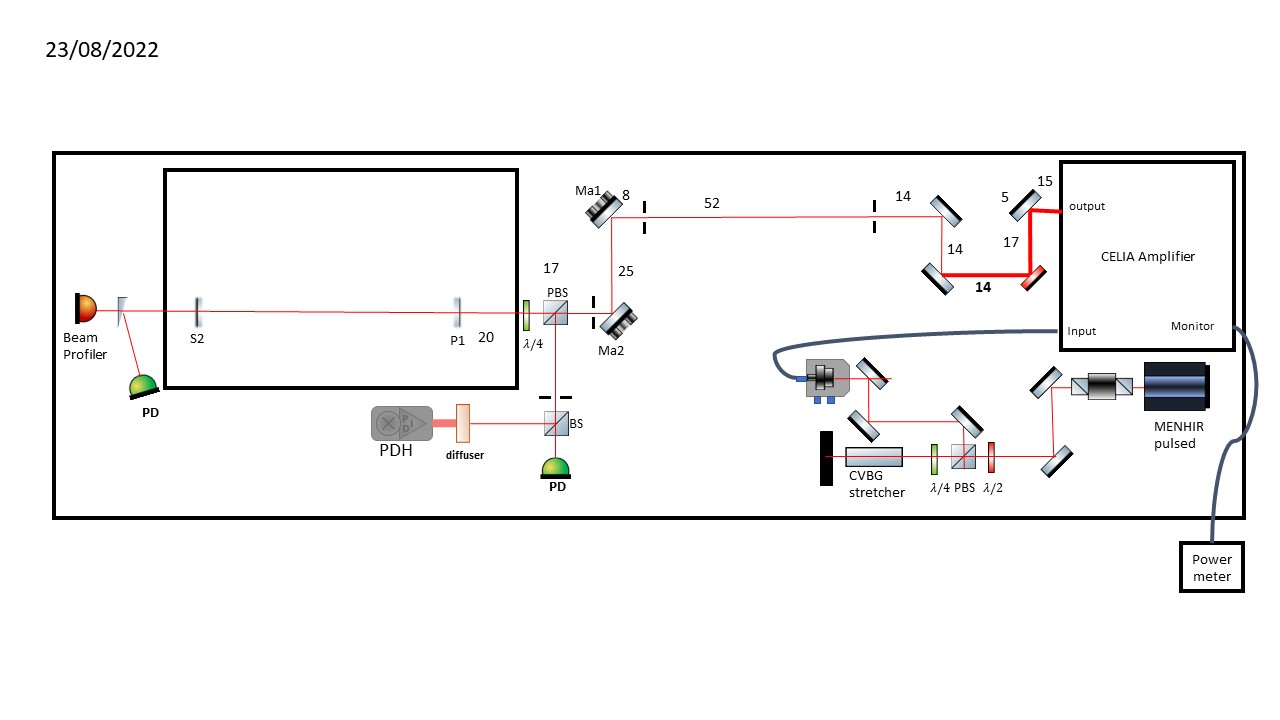
I placed a periscope to adjust the high of the beam from the amplifier output from ~ 10 cm from the table to ~ 15 cm
a dichroic mirror placed after it to reject the pump laser, all the mirrors on the path to the cavity were replaced with dielectric mirrors BB01-E03
the length of the path from the amplifier output to the cavity coupling mirror ~ 2 meters
setup defines the different optics placed in the path
Note: the beam goes all the way to the cavity, put it is not yet optimized to the irises.
| Manar Amer wrote: |
|
Beam divergence was measured using a method called "Focal Length Divergence Measurement Method"
Where a lens of a known focal length is placed on the beam path and the beam waist is measured at the focal distance using a beam profiler.
We ramped the power up to 10 W
for a focal length = 400 mm,
we measured a FWHM = 2.1 mm,
corresponding to a divergence = 4.45 mrad (edit : wrong software use)
for comparison, we measured the FWHM 8.1 mm @ 1.55 m and extracted the divergence directly 4.46 mrad (edit : this measurement is wrong - wrong use of the software)
Note: better to use a lens of a focal lens higher than 100 mm (to reduce the error in the distance measured)
| Manar Amer wrote: |
|
The previous Sbox telescope was dismantled and the mechanical components cleaned.
its lenses are still in the mounts, it looks that two of them are spherical and two are cylindrical
2 are -100 mm and 2 are +150 mm, there is also a box containing fused silica lenses that could be used.
Note: at high power use only fused silica lenses not BK7 type
|
|
|
|
|
|
|
|
144
|
Tue Sep 6 17:47:40 2022 |
Ronic Chiche | Fixed | issue | lasers and optics | Optical room | unsuccessful telescope design :-( |
we wanted to calculate the right telescope with 2 spherical lenses.
1) we have the FP cavity mode size which is 0.58mm at the input mirror and 0.7mm at the output mirror.
2) we planned to measure the laser beam at the output of the amplifier working at P=1W (2nd stage ON only).
we did several measurements at different positions from the amplifier output.
for each of these measurements, we were able to fit the intensity profile I = I0 * exp(-2 *r^2 / w^2) on x or y axis, then we have w(z).
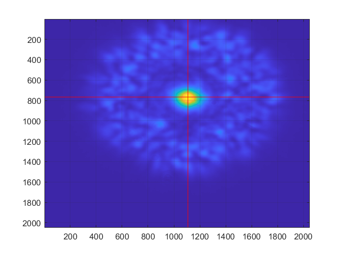
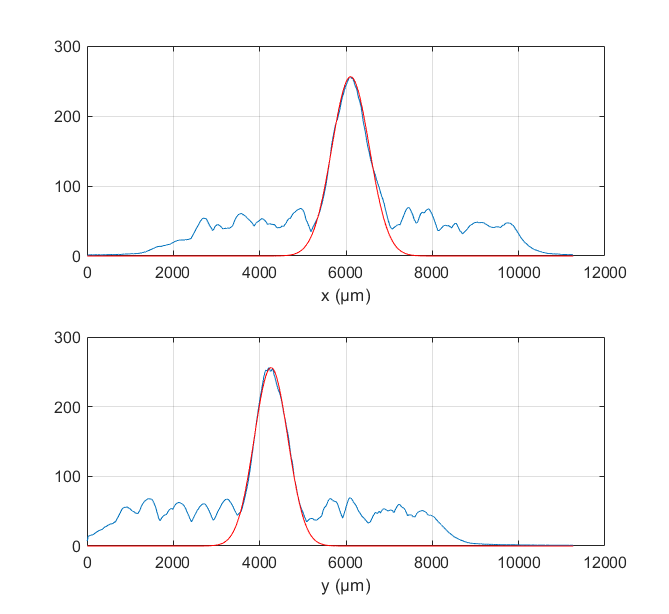
attached files give an example of the beam image at z=40mm and an example of the beam fits for w and y.
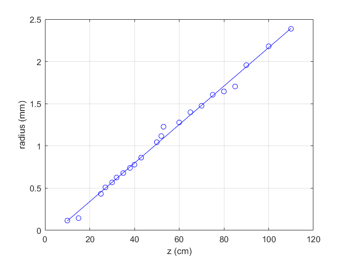
with all the w(z) measurements, we were able to fit the divergence of the beam => 2.3 mrad
attached file show the radius measurements and the divergence fit.
with this divergence, we should find a waist bigger than 140 µm (value for M²=1).
unfortunately the smallest beam radius measured is 116 µm which would give a M²<1 that is not allowed !
then it seems the measurements have not been done correctly... :-(
we will try to do them again... maybe at P=10W or 50W ?!? |
| Attachment 1: image_at_z_being_40mm.png
|
 |
| Attachment 2: beam_fit_at_z_being_40mm.png
|
 |
| Attachment 3: propagation_fit.png
|
 |
|
143
|
Mon Sep 5 18:06:53 2022 |
Manar Amer | Fixed | report | lasers and optics | Optical room | Telescope / amplifier output |
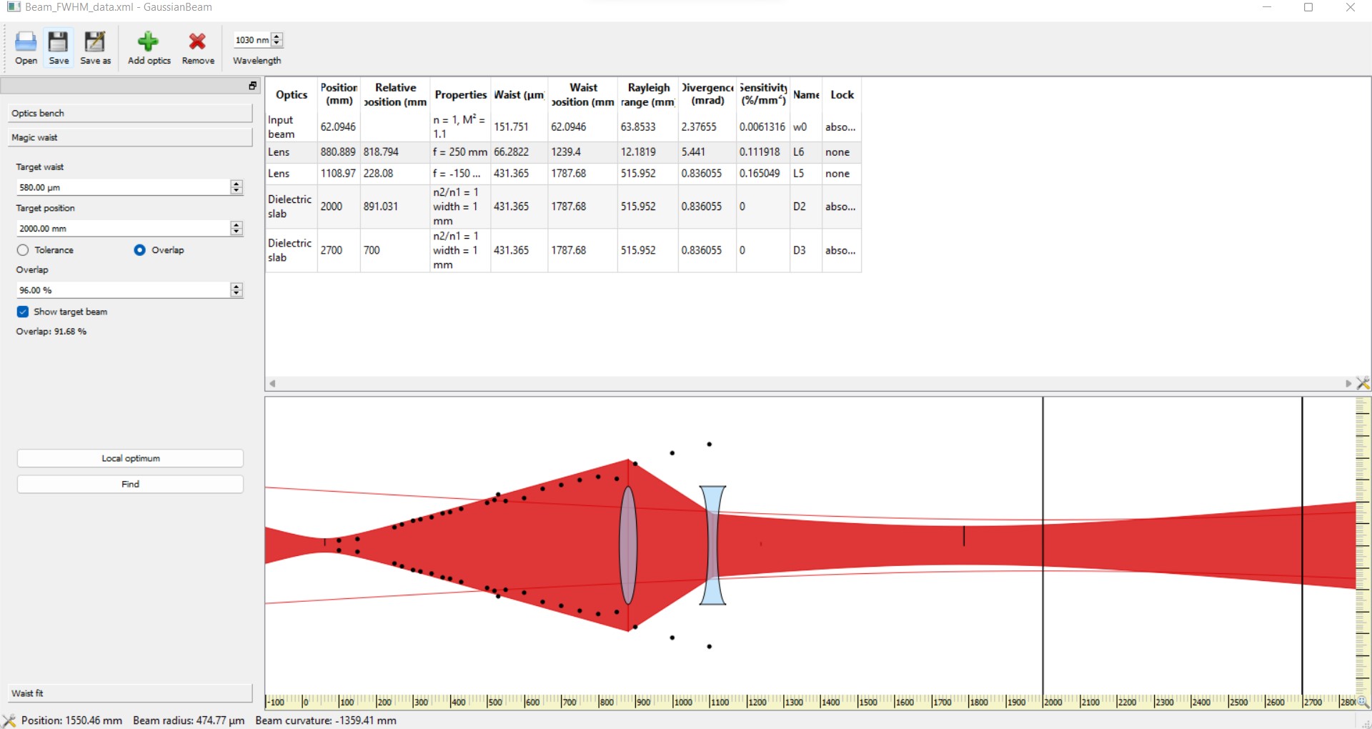
Am adjustment on the lenses position to have a smaller waist.
+ 250 mm @ 88 cm from amplifier
-150 mm @ 111 cm from amplifier
the overlap with this placement is ~ 91%
the measured beam FWHM at the injection point M1 estimated to be ~ 0.94 mm
waist = 0.85*0.94 = 0.79 mm , it is still much larger than the needed 0.58 mm radius waist.
There is an improvement in reducing higher order modes, but the fundamental is still too weak to see, we observe higher order even modes 11 , 44 , ...
| Manar Amer wrote: |
|
Note the correct beam divergence is approximately ~ 2.3 mrad
M2 = 1.1 in this fit, but it is not yet optimized !!!!! could be reason for not accurate telescope reading.
Have tInstalled a new telescope with lenses
250 mm @ 86.8 cm from amplifier ,
-150 mm @109 cm (~ 22 cm between lenses)
the beam waist measured at a point on the reflection which is relatively the same distance to the injection mirror and the beam was much smaller than before
@ ~ 2 meters from amplifier + telescope , FWHM = 1.2 mm , waist = 0.85 * FWHM = 1.02 mm
| Manar Amer wrote: |
|
Here is a view of beam propagation in the optical software : GaussianBeam
the red filled shape is the model of the CELIA amplifier beam propagation with a divergence of 4.46 mrad
(the 2 black dots is the measurement of the beam size without any lens to change the beam propagation).
the 2 black lines have been put at the input and output cavity mirrors position relative to the CELIA amplifier position, respectively 2m and 2.7m roughly.
the cavity mode radius should be 0.55mm and 0.7mm respectively.
the cavity mode shape is represented by the 2 red lines (very close to the red filled shape which is the beam).
the most simple working telescope could be a +250 lens at 280mm from the CELIA amplifier.
it gives a beam radius of 0.53mm at the input mirror and 0.64mm at the output mirror.
the overlapping is more than 99%
the 2nd file is the GaussianBeam file.
| Manar Amer wrote: |
|
I placed a periscope to adjust the high of the beam from the amplifier output from ~ 10 cm from the table to ~ 15 cm
a dichroic mirror placed after it to reject the pump laser, all the mirrors on the path to the cavity were replaced with dielectric mirrors BB01-E03
the length of the path from the amplifier output to the cavity coupling mirror ~ 2 meters
setup defines the different optics placed in the path
Note: the beam goes all the way to the cavity, put it is not yet optimized to the irises.
| Manar Amer wrote: |
|
Beam divergence was measured using a method called "Focal Length Divergence Measurement Method"
Where a lens of a known focal length is placed on the beam path and the beam waist is measured at the focal distance using a beam profiler.
We ramped the power up to 10 W
for a focal length = 400 mm,
we measured a FWHM = 2.1 mm,
corresponding to a divergence = 4.45 mrad (edit : wrong software use)
for comparison, we measured the FWHM 8.1 mm @ 1.55 m and extracted the divergence directly 4.46 mrad (edit : this measurement is wrong - wrong use of the software)
Note: better to use a lens of a focal lens higher than 100 mm (to reduce the error in the distance measured)
| Manar Amer wrote: |
|
The previous Sbox telescope was dismantled and the mechanical components cleaned.
its lenses are still in the mounts, it looks that two of them are spherical and two are cylindrical
2 are -100 mm and 2 are +150 mm, there is also a box containing fused silica lenses that could be used.
Note: at high power use only fused silica lenses not BK7 type
|
|
|
|
|
|
| Attachment 1: 20220905_Telescope_lense_placement.jpg
|
 |
|
142
|
Fri Sep 2 18:10:10 2022 |
Manar Amer | Fixed | report | lasers and optics | Optical room | Telescope / amplifier output |
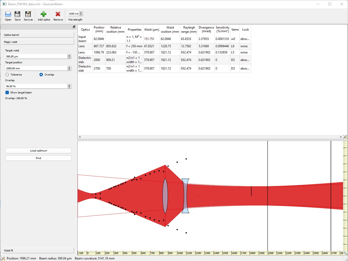
Note the correct beam divergence is approximately ~ 2.3 mrad
M2 = 1.1 in this fit, but it is not yet optimized !!!!! could be reason for not accurate telescope reading.
Have tInstalled a new telescope with lenses
250 mm @ 86.8 cm from amplifier ,
-150 mm @109 cm (~ 22 cm between lenses)
the beam waist measured at a point on the reflection which is relatively the same distance to the injection mirror and the beam was much smaller than before
@ ~ 2 meters from amplifier + telescope , FWHM = 1.2 mm , waist = 0.85 * FWHM = 1.02 mm
| Manar Amer wrote: |
|
Here is a view of beam propagation in the optical software : GaussianBeam
the red filled shape is the model of the CELIA amplifier beam propagation with a divergence of 4.46 mrad
(the 2 black dots is the measurement of the beam size without any lens to change the beam propagation).
the 2 black lines have been put at the input and output cavity mirrors position relative to the CELIA amplifier position, respectively 2m and 2.7m roughly.
the cavity mode radius should be 0.55mm and 0.7mm respectively.
the cavity mode shape is represented by the 2 red lines (very close to the red filled shape which is the beam).
the most simple working telescope could be a +250 lens at 280mm from the CELIA amplifier.
it gives a beam radius of 0.53mm at the input mirror and 0.64mm at the output mirror.
the overlapping is more than 99%
the 2nd file is the GaussianBeam file.
| Manar Amer wrote: |
|
I placed a periscope to adjust the high of the beam from the amplifier output from ~ 10 cm from the table to ~ 15 cm
a dichroic mirror placed after it to reject the pump laser, all the mirrors on the path to the cavity were replaced with dielectric mirrors BB01-E03
the length of the path from the amplifier output to the cavity coupling mirror ~ 2 meters
setup defines the different optics placed in the path
Note: the beam goes all the way to the cavity, put it is not yet optimized to the irises.
| Manar Amer wrote: |
|
Beam divergence was measured using a method called "Focal Length Divergence Measurement Method"
Where a lens of a known focal length is placed on the beam path and the beam waist is measured at the focal distance using a beam profiler.
We ramped the power up to 10 W
for a focal length = 400 mm,
we measured a FWHM = 2.1 mm,
corresponding to a divergence = 4.45 mrad (edit : wrong software use)
for comparison, we measured the FWHM 8.1 mm @ 1.55 m and extracted the divergence directly 4.46 mrad (edit : this measurement is wrong - wrong use of the software)
Note: better to use a lens of a focal lens higher than 100 mm (to reduce the error in the distance measured)
| Manar Amer wrote: |
|
The previous Sbox telescope was dismantled and the mechanical components cleaned.
its lenses are still in the mounts, it looks that two of them are spherical and two are cylindrical
2 are -100 mm and 2 are +150 mm, there is also a box containing fused silica lenses that could be used.
Note: at high power use only fused silica lenses not BK7 type
|
|
|
|
|
| Attachment 1: Ampli_Celia_2.3mrad_divergence_New_Telescope.jpg
|
 |
| Attachment 2: Beam_waist_at_injection_image.jpg
|
 |
|
141
|
Fri Sep 2 17:50:21 2022 |
Manar Amer | Fixed | report | lasers and optics | Optical room | Telescope / amplifier output |
removing the reading which is not correct (wrong use of software)
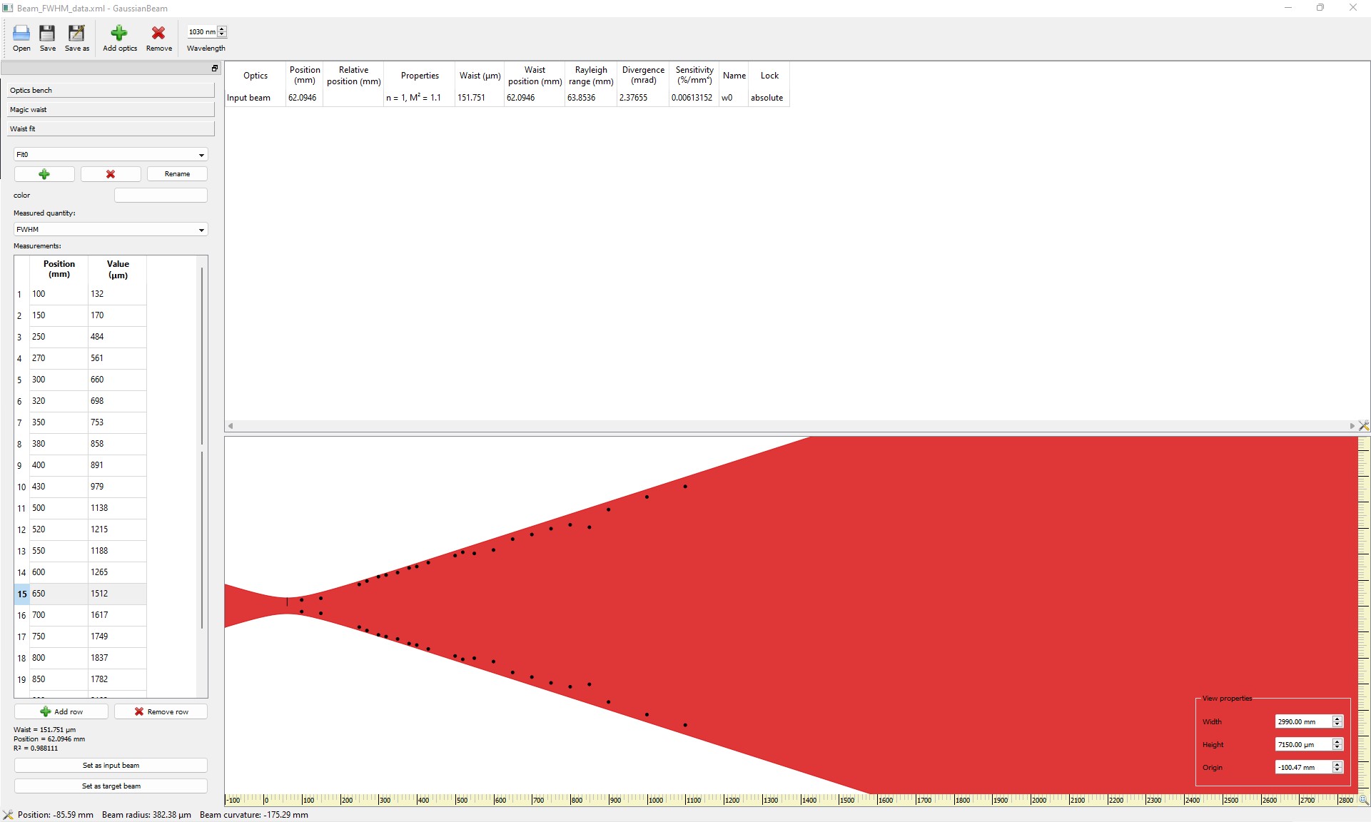
redone a reading similar using a lens of focal 250 mm got a FWHM-X = 0.64 mm , FWHM-Y = 0.84 mm
using the vertical to calculate the divergence, we get divergence ~ 2.17 mrad which is closer to fit obtained for the beam profile by taking data points along the path
attached is also the amplifier beam data taken at different points and their fit using Gaussian beam software
for a focal length = 400 mm,
we measured a FWHM = 2.1 mm,
corresponding to a divergence = 4.45 mrad
| Manar Amer wrote: |
|
Beam divergence was measured using a method called "Focal Length Divergence Measurement Method"
Where a lens of a known focal length is placed on the beam path and the beam waist is measured at the focal distance using a beam profiler.
We ramped the power up to 10 W
for a focal length = 400 mm,
we measured a FWHM = 2.1 mm,
corresponding to a divergence = 4.45 mrad (edit : wrong software use)
for comparison, we measured the FWHM 8.1 mm @ 1.55 m and extracted the divergence directly 4.46 mrad (edit : this measurement is wrong - wrong use of the software)
Note: better to use a lens of a focal lens higher than 100 mm (to reduce the error in the distance measured)
| Manar Amer wrote: |
|
The previous Sbox telescope was dismantled and the mechanical components cleaned.
its lenses are still in the mounts, it looks that two of them are spherical and two are cylindrical
2 are -100 mm and 2 are +150 mm, there is also a box containing fused silica lenses that could be used.
Note: at high power use only fused silica lenses not BK7 type
|
|
|
| Attachment 1: Beam_Profile_Fit_using_gaussian_Beam.jpg
|
 |
| Attachment 2: Beam_Profile_Fit_using_gaussian_Beam.xml
|
<?xml version="1.0" encoding="UTF-8"?>
<!DOCTYPE gaussianBeam>
<gaussianBeam version="1.1">
    <bench id="0">
        <wavelength>1.03e-06</wavelength>
        <leftBoundary>-0.1</leftBoundary>
        <rightBoundary>4</rightBoundary>
        <targetBeam id="0">
            <position>2</position>
            <waist>0.00058</waist>
            <positionTolerance>0.1</positionTolerance>
            <waistTolerance>0.05</waistTolerance>
            <minOverlap>0.96</minOverlap>
            <overlapCriterion>1</overlapCriterion>
        </targetBeam>
        <beamFit id="0">
            <name>Fit0</name>
            <dataType>3</dataType>
            <color>4278190080</color>
            <data id="0">
                <position>0.1</position>
                <value>0.000132</value>
            </data>
            <data id="1">
                <position>0.15</position>
                <value>0.00017</value>
            </data>
            <data id="2">
                <position>0.25</position>
                <value>0.000484</value>
            </data>
            <data id="3">
                <position>0.27</position>
                <value>0.000561</value>
            </data>
            <data id="4">
                <position>0.3</position>
                <value>0.00066</value>
            </data>
            <data id="5">
                <position>0.32</position>
                <value>0.000698</value>
            </data>
            <data id="6">
                <position>0.35</position>
                <value>0.000753</value>
            </data>
            <data id="7">
                <position>0.38</position>
                <value>0.000858</value>
            </data>
            <data id="8">
                <position>0.4</position>
                <value>0.000891</value>
            </data>
            <data id="9">
                <position>0.43</position>
                <value>0.000979</value>
            </data>
            <data id="10">
                <position>0.5</position>
                <value>0.001138</value>
            </data>
            <data id="11">
                <position>0.52</position>
                <value>0.001215</value>
            </data>
            <data id="12">
                <position>0.55</position>
                <value>0.001188</value>
            </data>
            <data id="13">
                <position>0.6</position>
                <value>0.001265</value>
            </data>
            <data id="14">
                <position>0.65</position>
                <value>0.001512</value>
            </data>
            <data id="15">
                <position>0.7</position>
                <value>0.001617</value>
            </data>
            <data id="16">
                <position>0.75</position>
                <value>0.001749</value>
            </data>
            <data id="17">
                <position>0.8</position>
                <value>0.001837</value>
            </data>
            <data id="18">
                <position>0.85</position>
                <value>0.001782</value>
            </data>
            <data id="19">
                <position>0.9</position>
                <value>0.002183</value>
            </data>
            <data id="20">
                <position>1</position>
                <value>0.002469</value>
            </data>
            <data id="21">
                <position>1.1</position>
                <value>0.002706</value>
            </data>
        </beamFit>
        <beamFit id="1">
            <name>Fit4</name>
            <dataType>1</dataType>
            <color>0</color>
            <data id="0">
                <position>0</position>
                <value>0</value>
            </data>
            <data id="1">
                <position>0</position>
                <value>0</value>
            </data>
            <data id="2">
                <position>0</position>
                <value>0</value>
            </data>
        </beamFit>
        <opticsList>
            <inputBeam id="2">
                <waist>0.000151751</waist>
                <index>1</index>
                <M2>1.1</M2>
                <position>0.0620946</position>
                <name>w0</name>
                <absoluteLock>1</absoluteLock>
            </inputBeam>
        </opticsList>
    </bench>
    <view id="0" bench="0">
        <horizontalRange>2.99</horizontalRange>
        <verticalRange>0.00715</verticalRange>
        <origin>-0.100473</origin>
        <showTargetBeam id="0">0</showTargetBeam>
    </view>
</gaussianBeam>
|
|
140
|
Wed Aug 31 18:14:51 2022 |
Ronic Chiche | Fixed | info | lasers and optics | Optical room | 2nd stage CELIA amplifier |
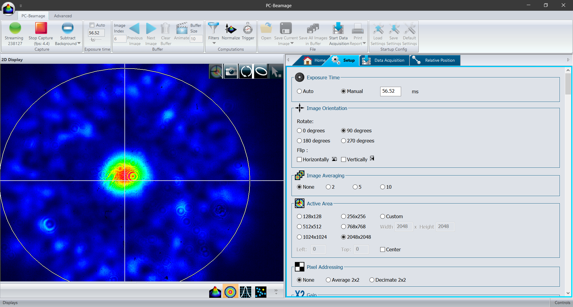
today we did several test with the Dichroic shortpass mirror (Thorlabs DMSP1000) and with a 10nm optical filter around 1030nm (which works in tranmission at AOI=0).
one used the dichroic mirror in reflection: one should cut the pump @970-990nm and we should keep only the signal @1030nm.
but we still saw plenty spots around the central beam (see the image).
adding the 10nm optical filter on the camera, the image did not change !
then we confirmed the whole signal (centered beam + spots) are well @1030nm.
this spots could be the remaining high order modes of the large fiber used for the 3rd stage of the amplifier.
| Ronic Chiche wrote: |
|
today, we measured the 2nd stage CELIA amplifier pump wavelength : 970-990 nm
|
|
| Attachment 1: image_faisceau_multimode_@1030nm.PNG
|
 |
|
139
|
Tue Aug 30 17:48:39 2022 |
Ronic Chiche | Fixed | info | lasers and optics | Optical room | 2nd stage CELIA amplifier |
today, we measured the 2nd stage CELIA amplifier pump wavelength : 970-990 nm |
| Attachment 1: 2nd_stage_pump_wavelength.jpg
|
 |
|
138
|
Wed Aug 24 10:45:24 2022 |
Manar Amer | Fixed | report | lasers and optics | Optical room | 2 Mirror Setup @ 216.6 MHz |
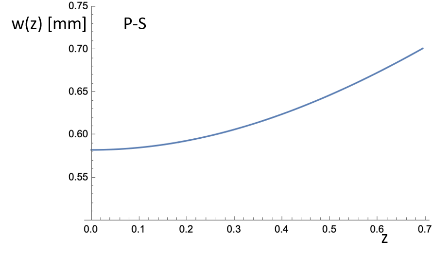
Adding information about the 2 mirror cavity setup (plan - spherical) that is currently installed.
From Aurélien at the start of the manipulation.
@ 0 is where the injection mirror is located
| Manar Amer wrote: |
|
The SBox cavity setup was changed to have only 2 mirrors M1 plane and M2 spherical, both from ThomX
Distance between the mirror ~ 72 cm , increased from 70 cm to take into account the thickness of the ThomX mirrors
Two lenses (300 mm @ 50 cm , 200 @ 104 cm) were placed to have the beam radius ~ 0.55 mm.
The cavity was locked with a coupling of 60 %, for Finesse measurement the sweep was taken over 100 KHz of 2 seconds.
FSR ~ 210.00 MHz, line width ~ 8.56 KHz, Finesse ~ 24 500 .
|
|
| Attachment 1: manip2miroirs.pptx
|
| Attachment 2: 2mirror_plan_shperical_beam_size.png
|
 |
|
137
|
Wed Aug 24 10:39:58 2022 |
Manar Amer | Fixed | report | lasers and optics | Optical room | Telescope / amplifier output |
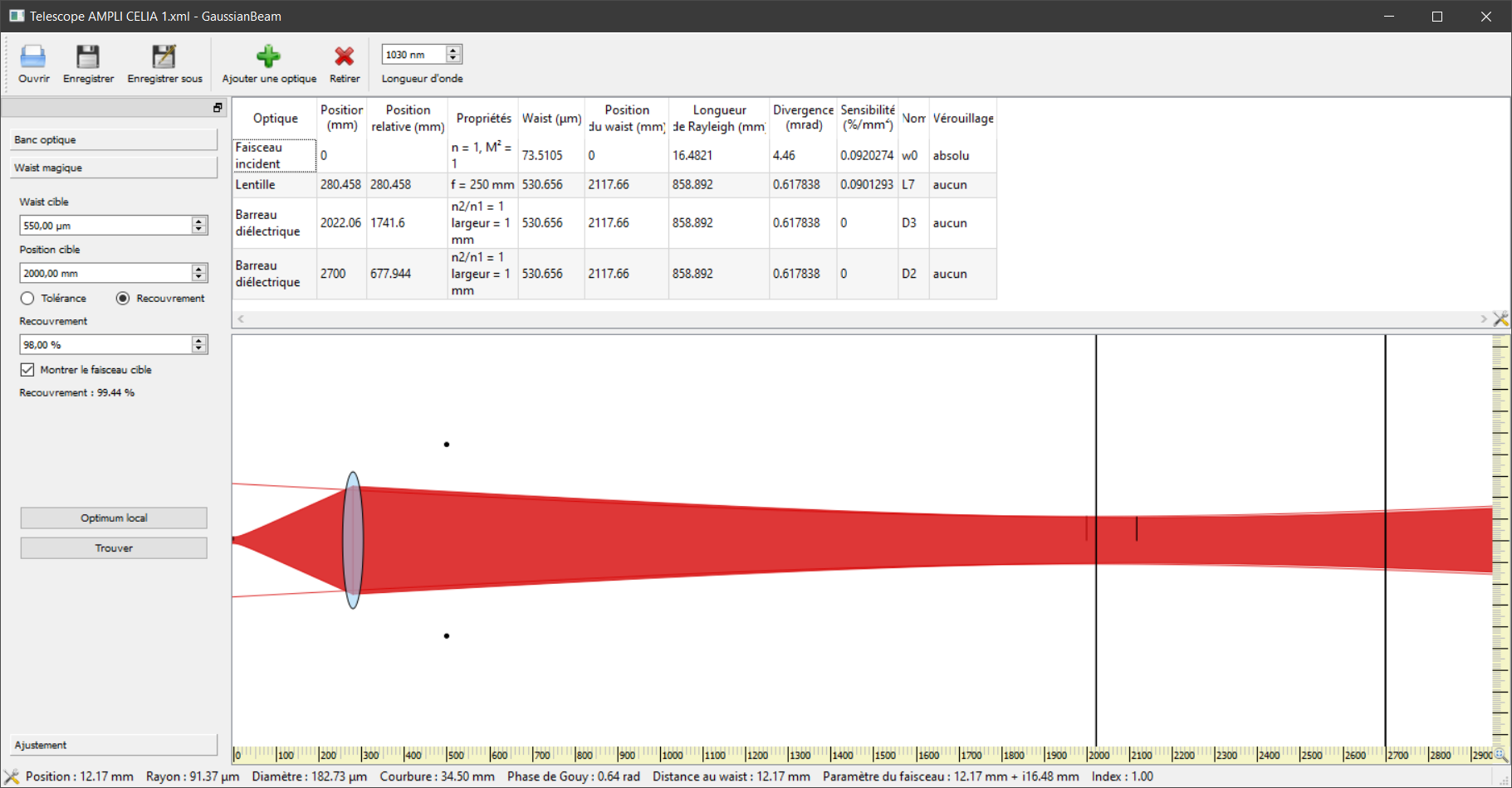
Here is a view of beam propagation in the optical software : GaussianBeam
the red filled shape is the model of the CELIA amplifier beam propagation with a divergence of 4.46 mrad
(the 2 black dots is the measurement of the beam size without any lens to change the beam propagation).
the 2 black lines have been put at the input and output cavity mirrors position relative to the CELIA amplifier position, respectively 2m and 2.7m roughly.
the cavity mode radius should be 0.55mm and 0.7mm respectively.
the cavity mode shape is represented by the 2 red lines (very close to the red filled shape which is the beam).
the most simple working telescope could be a +250 lens at 280mm from the CELIA amplifier.
it gives a beam radius of 0.53mm at the input mirror and 0.64mm at the output mirror.
the overlapping is more than 99%
the 2nd file is the GaussianBeam file.
| Manar Amer wrote: |
|
I placed a periscope to adjust the high of the beam from the amplifier output from ~ 10 cm from the table to ~ 15 cm
a dichroic mirror placed after it to reject the pump laser, all the mirrors on the path to the cavity were replaced with dielectric mirrors BB01-E03
the length of the path from the amplifier output to the cavity coupling mirror ~ 2 meters
setup defines the different optics placed in the path
Note: the beam goes all the way to the cavity, put it is not yet optimized to the irises.
| Manar Amer wrote: |
|
Beam divergence was measured using a method called "Focal Length Divergence Measurement Method"
Where a lens of a known focal length is placed on the beam path and the beam waist is measured at the focal distance using a beam profiler.
We ramped the power up to 10 W
for a focal length = 400 mm,
we measured a FWHM = 2.1 mm,
corresponding to a divergence = 4.45 mrad (edit : wrong software use)
for comparison, we measured the FWHM 8.1 mm @ 1.55 m and extracted the divergence directly 4.46 mrad (edit : this measurement is wrong - wrong use of the software)
Note: better to use a lens of a focal lens higher than 100 mm (to reduce the error in the distance measured)
| Manar Amer wrote: |
|
The previous Sbox telescope was dismantled and the mechanical components cleaned.
its lenses are still in the mounts, it looks that two of them are spherical and two are cylindrical
2 are -100 mm and 2 are +150 mm, there is also a box containing fused silica lenses that could be used.
Note: at high power use only fused silica lenses not BK7 type
|
|
|
|
| Attachment 1: Capture.PNG
|
 |
| Attachment 2: Telescope_AMPLI_CELIA_1.xml
|
<?xml version="1.0" encoding="UTF-8"?>
<!DOCTYPE gaussianBeam>
<gaussianBeam version="1.1">
    <bench id="0">
        <wavelength>1.03e-06</wavelength>
        <leftBoundary>-0.1</leftBoundary>
        <rightBoundary>5</rightBoundary>
        <targetBeam id="0">
            <position>2</position>
            <waist>0.00055</waist>
            <positionTolerance>0.1</positionTolerance>
            <waistTolerance>0.05</waistTolerance>
            <minOverlap>0.98</minOverlap>
            <overlapCriterion>1</overlapCriterion>
        </targetBeam>
        <beamFit id="0">
            <name>Fit6</name>
            <dataType>1</dataType>
            <color>0</color>
            <data id="0">
                <position>0.5</position>
                <value>0.00444</value>
            </data>
            <data id="1">
                <position>0</position>
                <value>0</value>
            </data>
            <data id="2">
                <position>0</position>
                <value>0</value>
            </data>
        </beamFit>
        <opticsList>
            <inputBeam id="2">
                <waist>7.35105e-05</waist>
                <index>1</index>
                <M2>1</M2>
                <position>0</position>
                <name>w0</name>
                <absoluteLock>1</absoluteLock>
            </inputBeam>
            <lens id="24">
                <focal>0.25</focal>
                <position>0.280458</position>
                <name>L7</name>
                <absoluteLock>0</absoluteLock>
            </lens>
            <dielectricSlab id="26">
                <indexRatio>1</indexRatio>
                <width>0.001</width>
                <position>2.02206</position>
                <name>D3</name>
                <absoluteLock>0</absoluteLock>
            </dielectricSlab>
            <dielectricSlab id="23">
                <indexRatio>1</indexRatio>
                <width>0.001</width>
                <position>2.7</position>
                <name>D2</name>
                <absoluteLock>0</absoluteLock>
            </dielectricSlab>
        </opticsList>
    </bench>
    <view id="0" bench="0">
        <horizontalRange>3</horizontalRange>
        <verticalRange>0.01</verticalRange>
        <origin>0</origin>
        <showTargetBeam id="0">1</showTargetBeam>
    </view>
</gaussianBeam>
|
|
136
|
Tue Aug 23 17:37:38 2022 |
Manar Amer | Fixed | report | lasers and optics | Optical room | Telescope / amplifier output |
I placed a periscope to adjust the high of the beam from the amplifier output from ~ 10 cm from the table to ~ 15 cm
a dichroic mirror placed after it to reject the pump laser, all the mirrors on the path to the cavity were replaced with dielectric mirrors BB01-E03
the length of the path from the amplifier output to the cavity coupling mirror ~ 2 meters
setup defines the different optics placed in the path
Note: the beam goes all the way to the cavity, put it is not yet optimized to the irises.
| Manar Amer wrote: |
|
Beam divergence was measured using a method called "Focal Length Divergence Measurement Method"
Where a lens of a known focal length is placed on the beam path and the beam waist is measured at the focal distance using a beam profiler.
We ramped the power up to 10 W
for a focal length = 400 mm,
we measured a FWHM = 2.1 mm,
corresponding to a divergence = 4.45 mrad (edit : wrong software use)
for comparison, we measured the FWHM 8.1 mm @ 1.55 m and extracted the divergence directly 4.46 mrad (edit : this measurement is wrong - wrong use of the software)
Note: better to use a lens of a focal lens higher than 100 mm (to reduce the error in the distance measured)
| Manar Amer wrote: |
|
The previous Sbox telescope was dismantled and the mechanical components cleaned.
its lenses are still in the mounts, it looks that two of them are spherical and two are cylindrical
2 are -100 mm and 2 are +150 mm, there is also a box containing fused silica lenses that could be used.
Note: at high power use only fused silica lenses not BK7 type
|
|
|
| Attachment 1: 20220823_setup.jpg
|
 |
|
135
|
Mon Aug 22 18:39:13 2022 |
Manar Amer | Fixed | report | lasers and optics | Optical room | Amplifier output Beam Profile |
Beam divergence after amplifier 4.46 mrad
| Manar Amer wrote: |
|
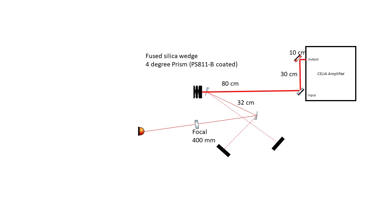
In preparation to measure the output beam profile from the amplifier at high power, I have placed two wedge mirrors just before the beam dump to be able to extract the beam.
One of the wedges was taken from ThomX bunker, also the HR and AR mirrors were taken to plic room in case we might need them
an updated setup is attached
|
|
|
134
|
Mon Aug 22 18:38:03 2022 |
Manar Amer | Fixed | report | lasers and optics | Optical room | Telescope / amplifier output |
Beam divergence was measured using a method called "Focal Length Divergence Measurement Method"
Where a lens of a known focal length is placed on the beam path and the beam waist is measured at the focal distance using a beam profiler.
We ramped the power up to 10 W
for a focal length = 400 mm,
we measured a FWHM = 2.1 mm,
corresponding to a divergence = 4.45 mrad (edit : wrong software use)
for comparison, we measured the FWHM 8.1 mm @ 1.55 m and extracted the divergence directly 4.46 mrad (edit : this measurement is wrong - wrong use of the software)
Note: better to use a lens of a focal lens higher than 100 mm (to reduce the error in the distance measured)
| Manar Amer wrote: |
|
The previous Sbox telescope was dismantled and the mechanical components cleaned.
its lenses are still in the mounts, it looks that two of them are spherical and two are cylindrical
2 are -100 mm and 2 are +150 mm, there is also a box containing fused silica lenses that could be used.
Note: at high power use only fused silica lenses not BK7 type
|
|
| Attachment 1: Focal_length_divergence_method.pdf
|
| Attachment 2: Beam_Profile_at_high_power_.jpg
|
 |
| Attachment 3: SBOX_CELIA_AMPLIFIER_Divergence_measurement.pdf
|
|
133
|
Fri Aug 19 16:36:18 2022 |
Manar Amer | Fixed | report | lasers and optics | Optical room | Telescope / amplifier output |
The previous Sbox telescope was dismantled and the mechanical components cleaned.
its lenses are still in the mounts, it looks that two of them are spherical and two are cylindrical
2 are -100 mm and 2 are +150 mm, there is also a box containing fused silica lenses that could be used.
Note: at high power use only fused silica lenses not BK7 type
|