| ID |
Date |
Author |
Status |
Type |
Category |
Location |
Title |
|
192
|
Mon Feb 26 08:58:33 2024 |
Xinyi Lu | Fixed | info | lasers and optics | Optical room | Menhir pulsed laser locking | Last week, Ronic and I focused on CEP measurements of the menhir laser.
- Measurements without Cavity Locking:
- Direct measurement of repetition rate (Frep) with a spectrum analyzer. Altering the laser pump current from 950mA to 850mA, Frep changed by +28Hz.
- Measurement of the variation of carrier-envelope frequency (Fceo) by beating with CW laser. Altering the laser pump current from 950mA to 850mA resulted in a beating frequency of n0*dFrep + dFceo = +/-2.4MHz, so dFceo ~ 50MHz.
- Measurement with Cavity Locking:
- Maintaining cavity locking, we changed the laser pump current and AOM frequency to record the transmitted power of 5 consecutive fundamental mode (TEM00) resonances.
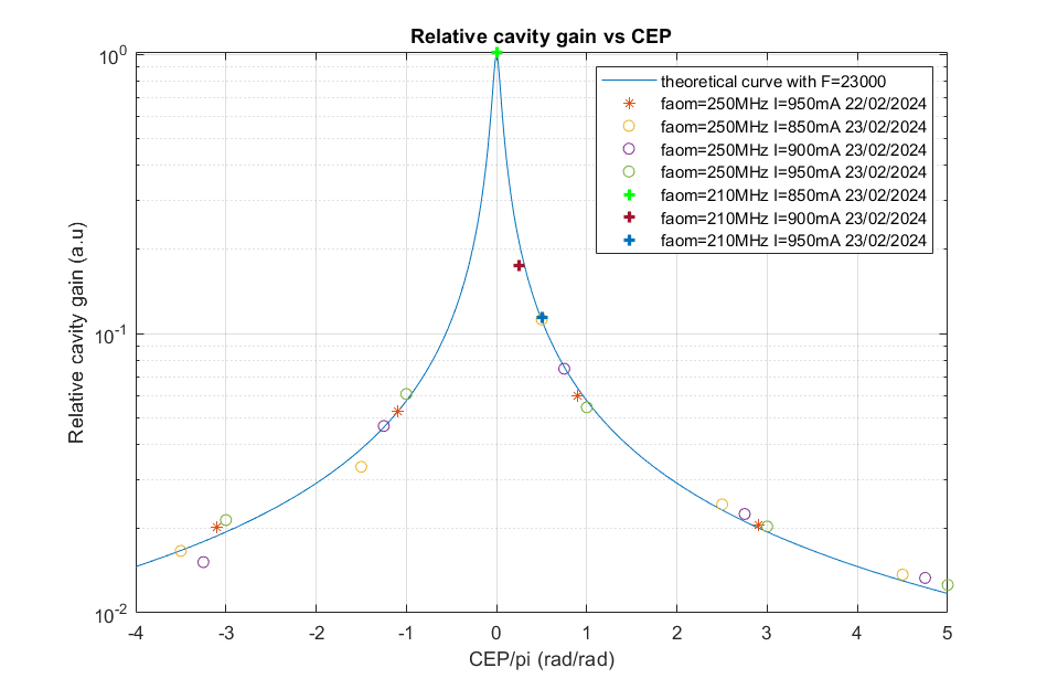
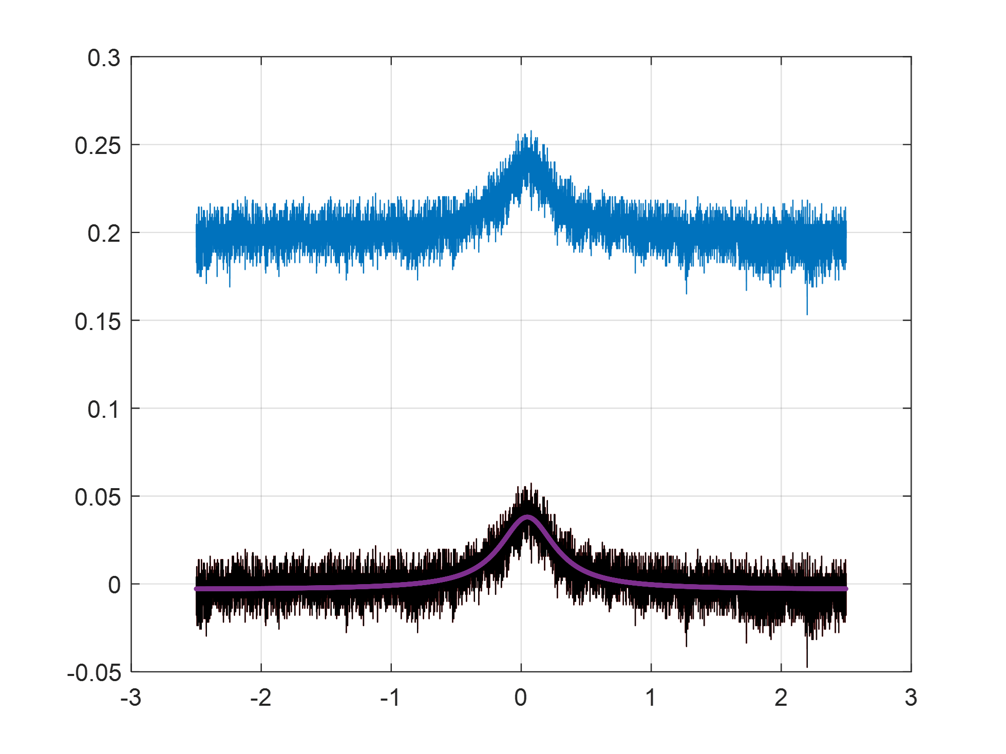
- The pump currents were set to 850 mA, 900 mA and 950 mA, and the AOM frequency were set to 210 MHz and 250 MHz. We then plotted the measured transmission amplitude values against the theoretical gain curve (see Figure 1).
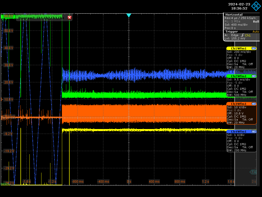
- By adjusting the CEP, we reach the top point on the curve, which is the maximum gain. At this point, the coupling frequency increases from 10% to 50% (see Figure 2).
- We observe that a 100mA change in pump current adjusts the CEP for pi/2, while changing the AOM frequency by +/-40MHz adjusts the CEP for pi. In summary, our CEP tuning range is about 3pi/2 (130 MHz) - not the full 2pi, but still probably giving us maximum gain.
- Next Steps:
- Investigate factors associated with changes in CEP, such as laser temperature or pressure.
- Discuss with Menhir the feasibility of expanding the laser pump current adjustment range (now limited to 100mA).
- Optimize AOM frequency and locking status, connect the amplifier.
| Xinyi Lu wrote: |
|
Here is a simulation of the relative FP-cavity gain vs the CEP for a Finesse of 23000 and taking into account the Menhir laser optical spectrum and several CVBG parameters.
I added the commented Matlab code to produce this plot.
| Xinyi Lu wrote: |
|
These days, Ronic, Daniele and I achieved stable cavity locking with the menhir pulsed laser.
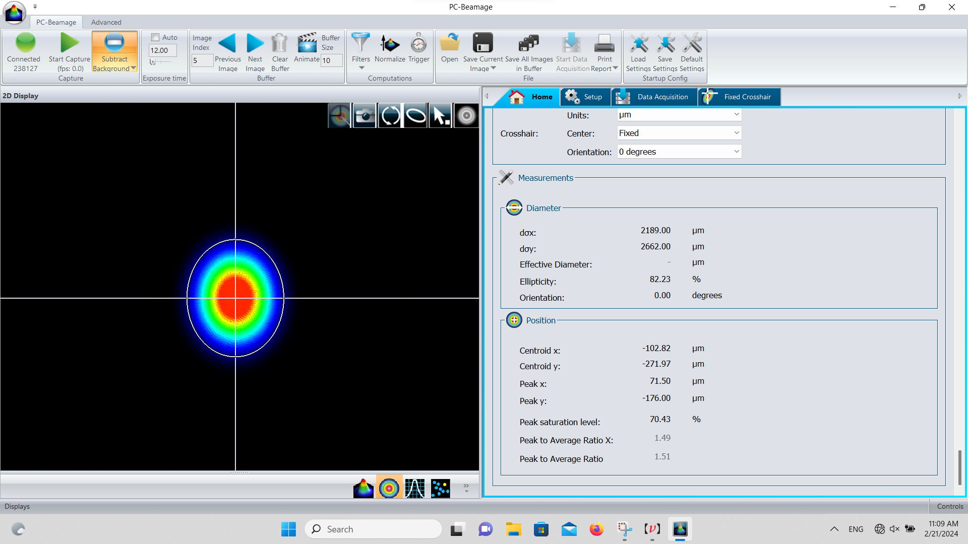
- After vacuuming, the current cavity finesse is now about 23,000. The diameter of the cavity mode is w_x=2.2mm, w_y=2.7mm.
- We had to compensate for frequency drift by manually adjusting the cavity length to keep locking.
Now the problem is that CEP's compensation range is not enough. The laser CEP is drifting from day to day. We adjusted the CEP by tuning the pump current of the menhir laser, but the adjustment range was not enough.
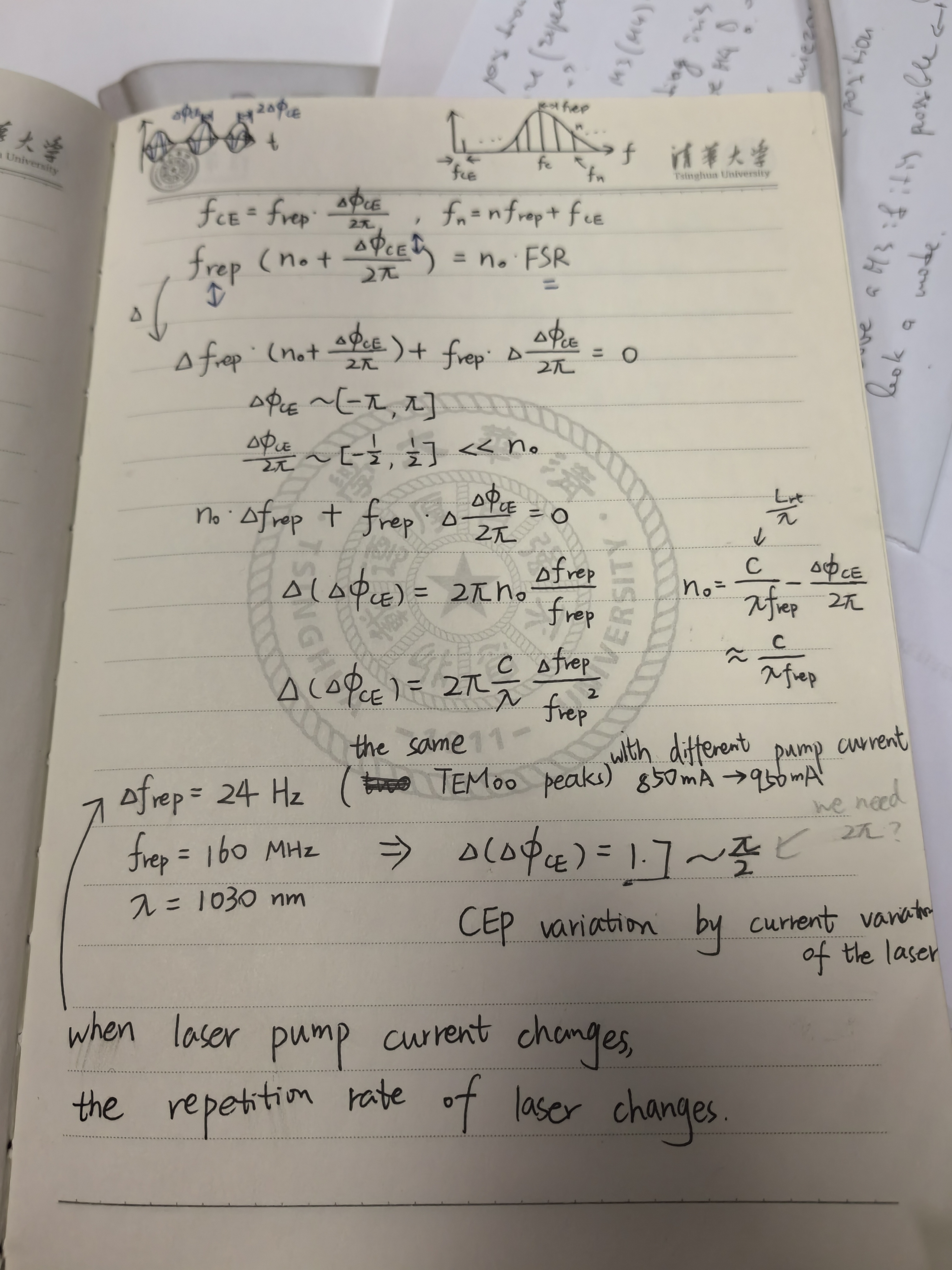
- The laser pump current is varied in the locking state and the variation of repetition rate is recorded. The current range is 850mA to 950mA and the repetition rate changes by 24 Hz. The calculation process is shown in Figure 3.
- By calculation, the variation of CEP caused by the variation of laser current is only π/2, which we hope is 2π.
- For Gamma Factory, the target FSR is 40 MHz, so the 4-pulse stack provides 4 times CEP tuning range to meet the requirements. But for our experiment, it seems not enough now.
The next step is to evaluate the gap to the maximum gain and draw the curve of CEP. Then we will discuss solutions.
|
|
|
| Attachment 1: Gain_vs_CEP.png
|  |
| Attachment 2: Screenshot_2024-02-23_0_183652.png
|  |
|
191
|
Wed Feb 21 18:09:11 2024 |
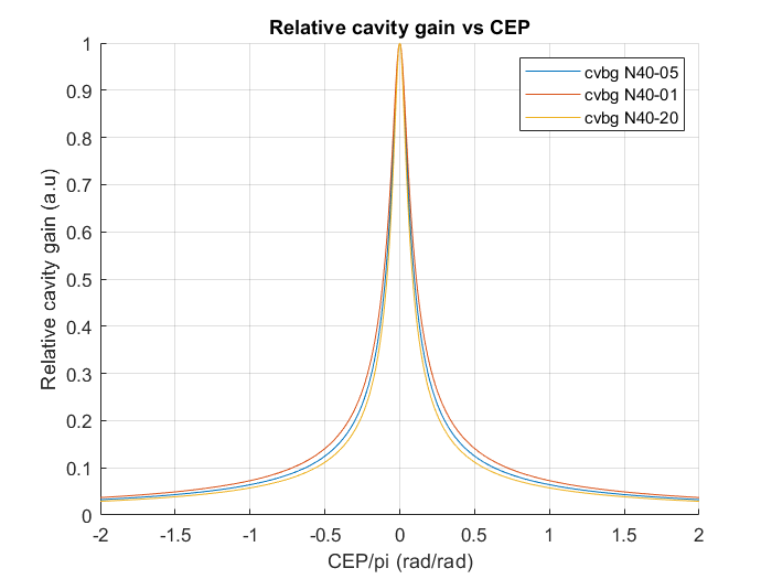
Xinyi Lu | Fixed | info | lasers and optics | Optical room | Menhir pulsed laser locking | Here is a simulation of the relative FP-cavity gain vs the CEP for a Finesse of 23000 and taking into account the Menhir laser optical spectrum and several CVBG parameters.
I added the commented Matlab code to produce this plot.
| Xinyi Lu wrote: |
|
These days, Ronic, Daniele and I achieved stable cavity locking with the menhir pulsed laser.
- After vacuuming, the current cavity finesse is now about 23,000. The diameter of the cavity mode is w_x=2.2mm, w_y=2.7mm.
- We had to compensate for frequency drift by manually adjusting the cavity length to keep locking.
Now the problem is that CEP's compensation range is not enough. The laser CEP is drifting from day to day. We adjusted the CEP by tuning the pump current of the menhir laser, but the adjustment range was not enough.
- The laser pump current is varied in the locking state and the variation of repetition rate is recorded. The current range is 850mA to 950mA and the repetition rate changes by 24 Hz. The calculation process is shown in Figure 3.
- By calculation, the variation of CEP caused by the variation of laser current is only π/2, which we hope is 2π.
- For Gamma Factory, the target FSR is 40 MHz, so the 4-pulse stack provides 4 times CEP tuning range to meet the requirements. But for our experiment, it seems not enough now.
The next step is to evaluate the gap to the maximum gain and draw the curve of CEP. Then we will discuss solutions.
|
|
| Attachment 1: Relative_cavity_gain_vs_CEP.png
|  |
| Attachment 2: Gain_vs_CEP.m
|
clear
clc

c=3e8;                      % speed of light

% laser parameters
lambda0=1031.6e-9;          % central wavelength (m)
dlambda0=6.2e-9;            % spectral LW (m)
Frep0=160.3e6;              % laser repetition rate (Hz)
CEP0=0;                     % arbitrary CEP value (rad)

% CVBG parameters
CVBG=3;                      % choose the version of the CVBG
switch CVBG
    case 1
        % N40-05
        lambda1=1031.61e-9;   % central wavelength (m)
        dlambda1=2.2e-9;      % spectral LW (m)
    case 2
        % N40-01
        lambda1=1031.55e-9;   % central wavelength (m)
        dlambda1=1.92e-9;     % spectral LW (m)
    case 3
        %N40-20
        lambda1=1031.64e-9;   % central wavelength (m)
        dlambda1=2.49e-9;     % spectral LW (m)
end
lambda_min=lambda1-dlambda1/2; % minimum wavelength limit of the CVBG
lambda_max=lambda1+dlambda1/2; % maximum wavelength limit of the CVBG

% wavelength vector
lambda=linspace(lambda0-5*dlambda0,lambda0+5*dlambda0,1e5);
% laser power vs wavelentgth
Plas=Plaser(lambda,lambda0,dlambda0,0,1);
% laser power after CVBG vs wavelentgth
Pcvbg=Plaser(lambda,lambda0,dlambda0,lambda_min,lambda_max);

figure(1)
clf
plot(lambda*1e9,Plas)
hold on
plot(lambda*1e9,Pcvbg)
grid on
xlabel('wavelength (nm)')
ylabel('laser power (a.u)')
title('laser spectral power before and after CVBG')
legend('before CVBG','after CVBG')

nmin=floor(c/lambda_max/Frep0);   % minimum laser resonance index
nmax=ceil(c/lambda_min/Frep0);    % maximum laser resonance index
nmean=(nmin+nmax)/2;              % average laser resonance index
nv=nmin:nmax;                     % vector of resonance indexes
flas=(nv+CEP0/2/pi)*Frep0;        % vector of laser frequencies
lambda=c./flas;                   % new vector of wavelength for the laser
% laser power after CVBG vs wavelentgth
Pcvbg=Plaser(lambda,lambda0,dlambda0,lambda_min,lambda_max);

figure(2)
clf
plot(lambda*1e9,Pcvbg)
grid on
xlabel('wavelength (nm)')
ylabel('laser power (a.u)')
title('laser spectral power after CVBG')

% FP-cavity description
FSR=Frep0;          % Free Spectral Range of the FP-cavity
F=23000;            % Finesse of the FP-cavity
LW=FSR/F;           % FP-cavity linewidth definition

N=1e3;              % Nb of CEP simulation steps
cepv=linspace(-2*pi,2*pi,N);    % CEP vector
Gcav=zeros(1,N);                % FP-cavity gain vector initialization
for k=1:N
    dfrep=-cepv(k)/2/pi/(nmean+cepv(k)/2/pi)*FSR; % dfrep = frep - FSR
    df=(nv-nmean).*dfrep;                      % df = flas(n) - n*FSR
    T=Airy(df,LW);                            % power FP-cavity gain vs df
    Gcav(k)=sum(T.*Pcvbg)/sum(Pcvbg);         % total FP-cavity gain
end

figure(3)
clf
hold on
plot(cepv/pi,Gcav)
grid on
xlabel('CEP/pi (rad/rad)')
ylabel('Relative cavity gain (a.u)')
title('Relative cavity gain vs CEP')
%legend('cvbg N40-05','cvbg N40-01','cvbg N40-20')

% Laser power after CVBG function
function Pcvbg=Plaser(lambda,lambda0,dlambda0,lambda_min,lambda_max)
Plas=sech(1.7625*(lambda-lambda0)/dlambda0).^2;
Tcvbg=lambda>=lambda_min & lambda<=lambda_max;
Pcvbg=Plas.*Tcvbg;
end

% FP-cavity Airy function
function T=Airy(df,LW)
T=1./(1+(2*df/LW).^2);
end
|
|
190
|
Wed Feb 21 17:33:59 2024 |
Xinyi Lu | Fixed | info | lasers and optics | Optical room | Menhir pulsed laser locking | These days, Ronic, Daniele and I achieved stable cavity locking with the menhir pulsed laser.
- After vacuuming, the current cavity finesse is now about 23,000. The diameter of the cavity mode is w_x=2.2mm, w_y=2.7mm.
- We had to compensate for frequency drift by manually adjusting the cavity length to keep locking.
Now the problem is that CEP's compensation range is not enough. The laser CEP is drifting from day to day. We adjusted the CEP by tuning the pump current of the menhir laser, but the adjustment range was not enough.
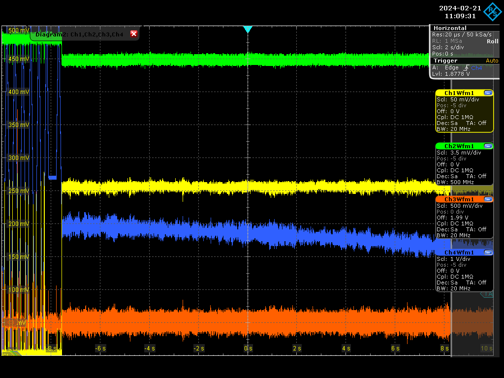
- The laser pump current is varied in the locking state and the variation of repetition rate is recorded. The current range is 850mA to 950mA and the repetition rate changes by 24 Hz. The calculation process is shown in Figure 3.
- By calculation, the variation of CEP caused by the variation of laser current is only π/2, which we hope is 2π.
- For Gamma Factory, the target FSR is 40 MHz, so the 4-pulse stack provides 4 times CEP tuning range to meet the requirements. But for our experiment, it seems not enough now.
The next step is to evaluate the gap to the maximum gain and draw the curve of CEP. Then we will discuss solutions.
|
| Attachment 1: Screenshot_2024-02-21_1_110931.png
|  |
| Attachment 2: Screenshot_2024-02-21_110934.png
|  |
| Attachment 3: calculation.jpg
|  |
|
189
|
Wed Feb 14 17:20:26 2024 |
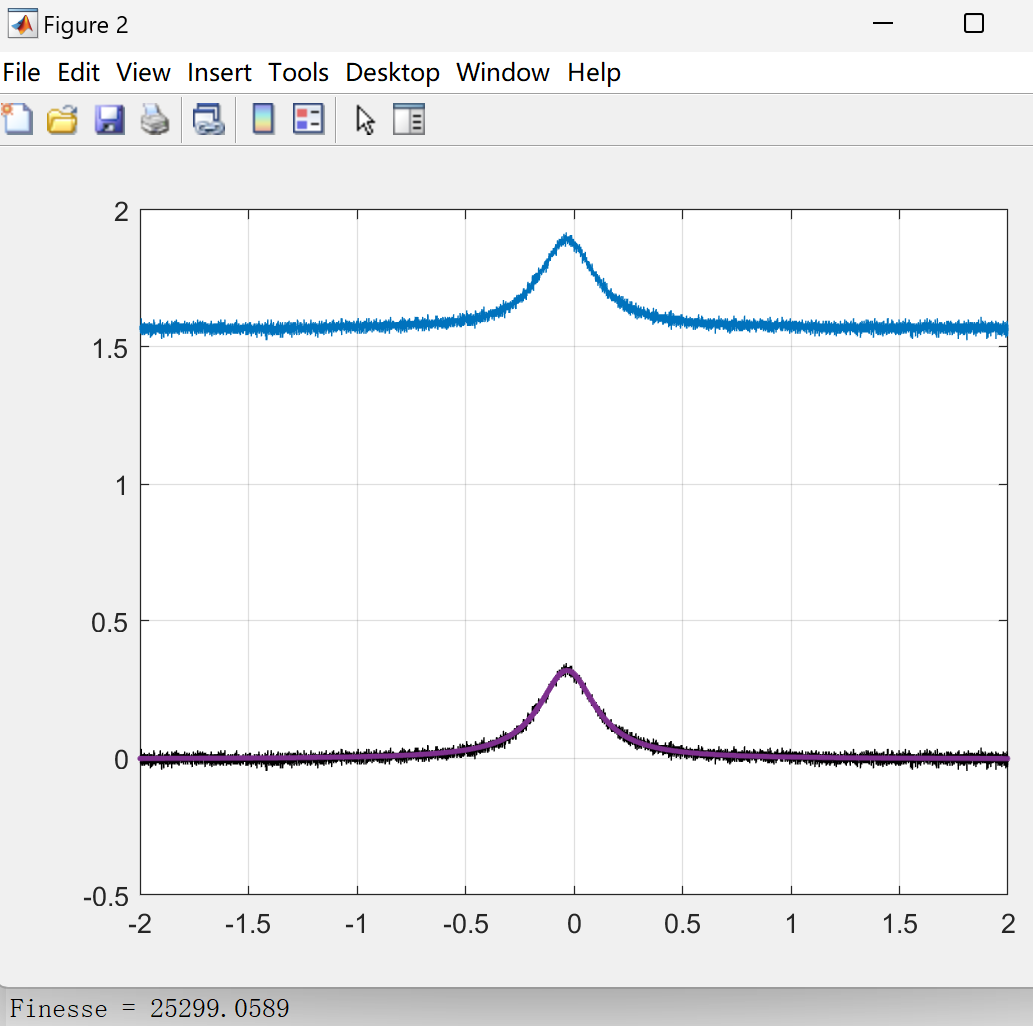
Xinyi Lu | Fixed | info | lasers and optics | Optical room | Cleaning of Mirrors | - Today, Daniele and I cleaned the cavity inside, recleaned the M2 and M4 and their mounts, optimized the locking, and the finesse is now about 25,000.
- Although it's lower than the expected 30,000-40,000, we decided to move on to the next step. In addition, the mount of M4 is near the end of the tuning range and may cause instability at high power.
- We adjusted the cavity length to match the repetition rate of the pulsed laser, and the FSR in air is 160.265 MHz.
- Tomorrow, we'll turn on the vacuum and use the pulsed laser to get resonance.
| Xinyi Lu wrote: |
|
Today, Daniele and I cleaned mirrors one by one using pure water, alcohol, and the spin coater. Here are the measurements of finesse each time:
1. Initial value: 14,076
2. Clean Mirror 2: 20,606
3. Clean Mirror 4: 18,750
4. Clean Mirror 3: 18,762
5. Clean Mirror 1: 18,563
6. Reclean Mirror 4: 15,226 (unstable lock)
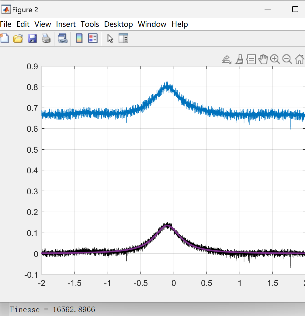
7. Reclean Mirror 4 again: 16,563 (unstable lock)
The finesse reached a maximum of 20,606 but finally was down. For the last two measurements, the locking state was unstable and noisy. Tomorrow we will optimize the locking status and re-measure.
|
|
| Attachment 1: F_25299.png
|  |
|
188
|
Tue Feb 13 17:33:28 2024 |
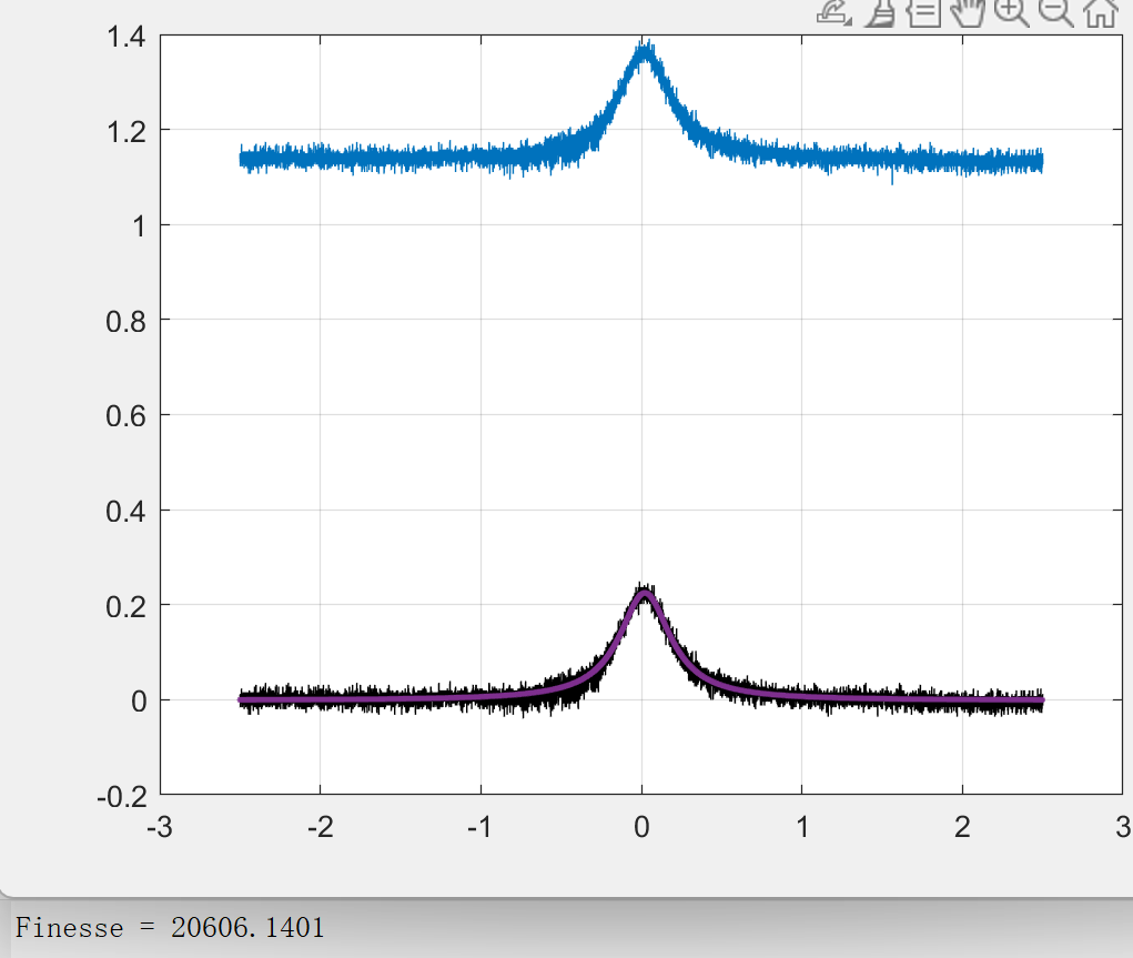
Xinyi Lu | Fixed | info | lasers and optics | Optical room | Cleaning of Mirrors | Today, Daniele and I cleaned mirrors one by one using pure water, alcohol, and the spin coater. Here are the measurements of finesse each time:
1. Initial value: 14,076
2. Clean Mirror 2: 20,606
3. Clean Mirror 4: 18,750
4. Clean Mirror 3: 18,762
5. Clean Mirror 1: 18,563
6. Reclean Mirror 4: 15,226 (unstable lock)
7. Reclean Mirror 4 again: 16,563 (unstable lock)
The finesse reached a maximum of 20,606 but finally was down. For the last two measurements, the locking state was unstable and noisy. Tomorrow we will optimize the locking status and re-measure.
| Xinyi Lu wrote: |
|
- Today we cleaned the environment and put the spin coater and microscope inside the airflow.
- Tomorrow, Daniele and I will clean the mirrors one by one using pure alcohol and water, and measure the finesse each time. If it does not improve, we will clean them with plasma.
|
|
| Attachment 1: 2nd_measurement_F20606.png
|  |
| Attachment 2: 7th_measurement__F16563_bad_locking.png
|  |
|
187
|
Mon Feb 12 17:17:04 2024 |
Xinyi Lu | Fixed | info | lasers and optics | Optical room | Cleaning of Mirrors | - Today we cleaned the environment and put the spin coater and microscope inside the airflow.
- Tomorrow, Daniele and I will clean the mirrors one by one using pure alcohol and water, and measure the finesse each time. If it does not improve, we will clean them with plasma.
| Xinyi Lu wrote: |
|
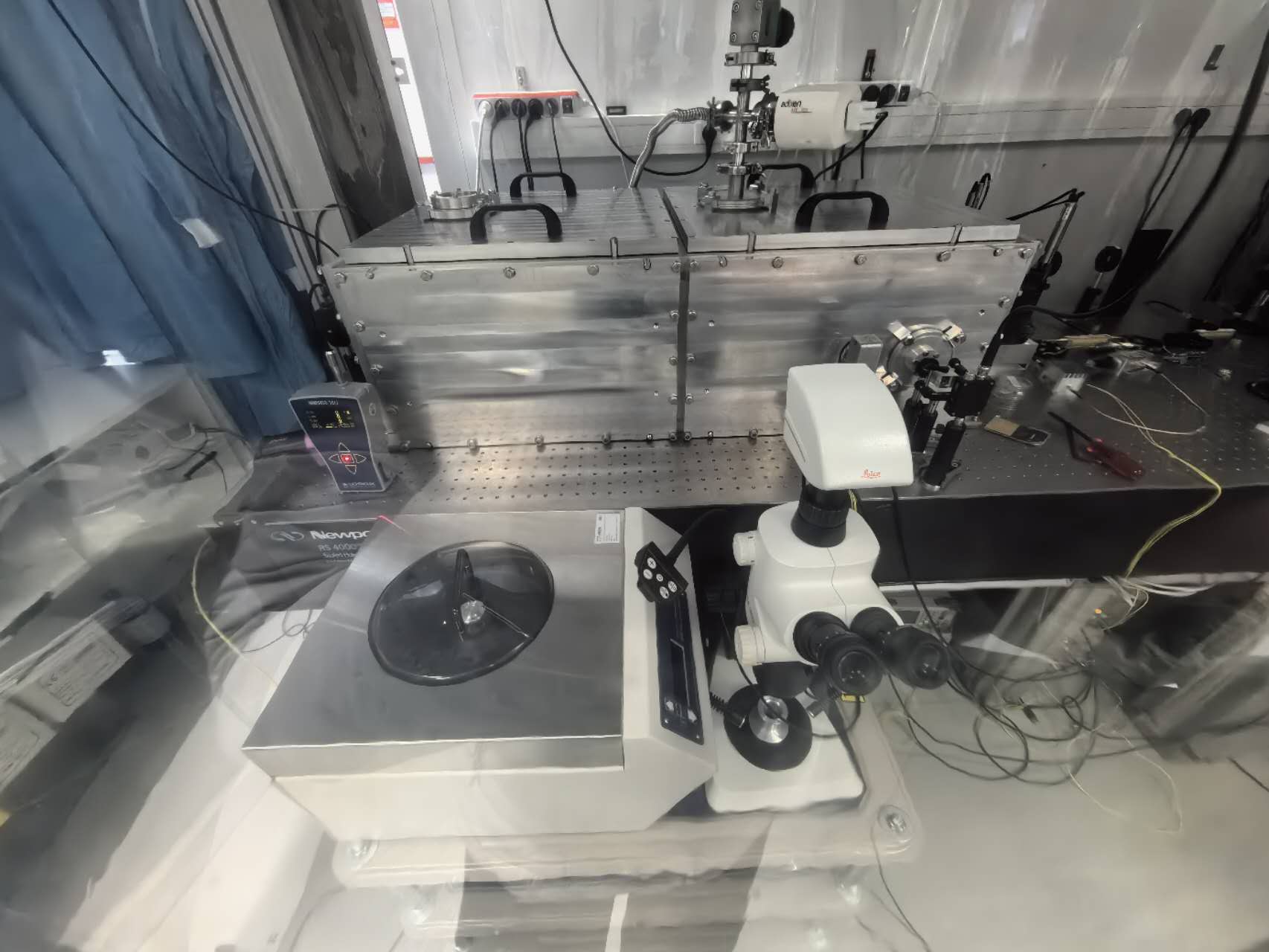
Today Daniele, Ronic and I cleaned the mirrors and locked the cavity. However, the finesse was only 13,000 because of the not clean enough environment and not pure enough alcohol and water.
We will carefully clean the environment, clean the mirrors again with pure alcohol and water and measure the finesse when I return. If it doesn't work, we will use plasma to clean the mirror. We have gone to the lab to confirm the plasma device and then we will study the best parameter settings: polarity, time, and current.
Have a nice weekend!
|
|
| Attachment 1: optical_room.jpg
|  |
|
186
|
Fri Jan 26 17:33:05 2024 |
Xinyi Lu | Fixed | info | lasers and optics | Optical room | Cleaning of Mirrors | Today Daniele, Ronic and I cleaned the mirrors and locked the cavity. However, the finesse was only 13,000 because of the not clean enough environment and not pure enough alcohol and water.
We will carefully clean the environment, clean the mirrors again with pure alcohol and water and measure the finesse when I return. If it doesn't work, we will use plasma to clean the mirror. We have gone to the lab to confirm the plasma device and then we will study the best parameter settings: polarity, time, and current.
Have a nice weekend! |
|
185
|
Wed Jan 24 20:33:27 2024 |
Xinyi Lu | Fixed | info | lasers and optics | Optical room | Install new mirrors | Yesterday we checked the mirrors with UV light and there was some dust on the mirrors, especially M2.
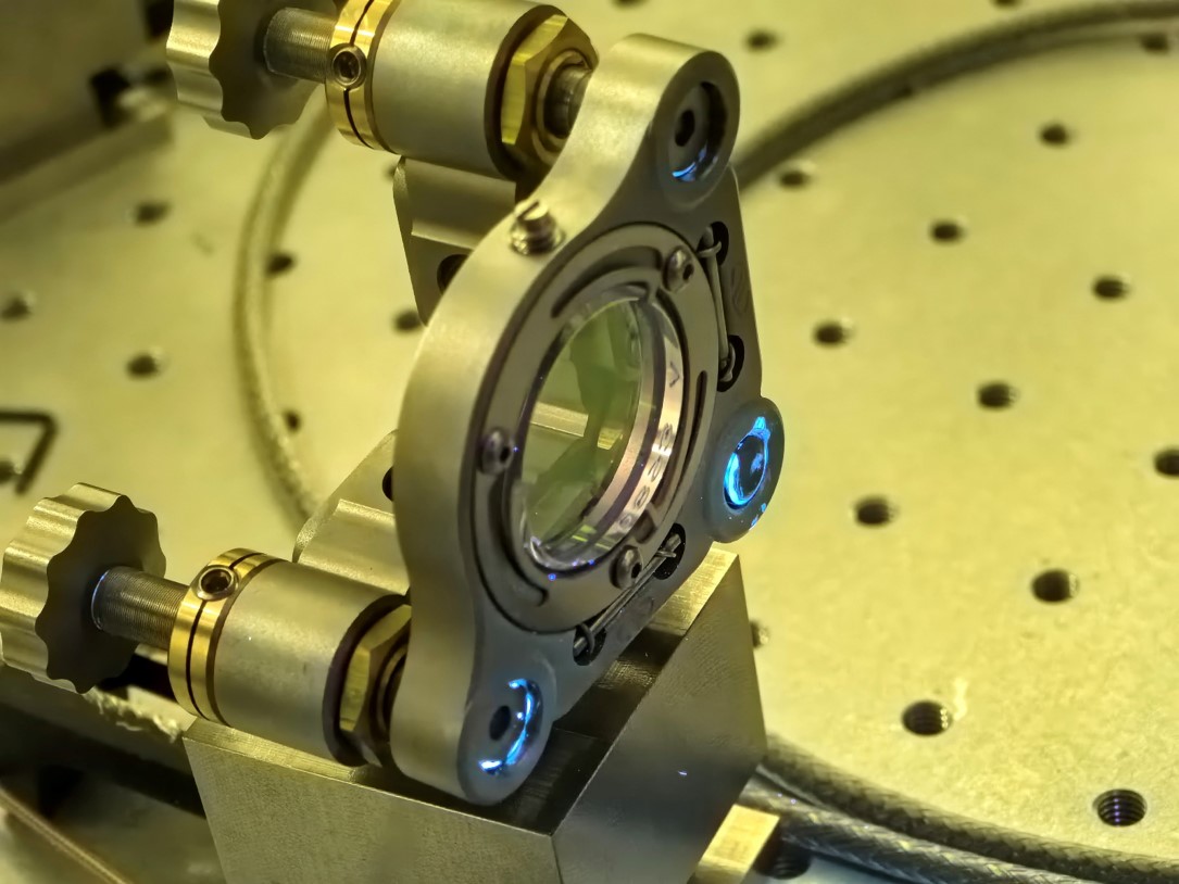
Today, Daniele, Ronic and I removed M2 and observed it with a microscope. It was indeed dirty, despite we were careful in installing it before. After that we cleaned it with alcohol and mirror paper, then with a spin coater and pure water. After cleaning, we observed it again and it was much better but not perfect. Then we installed the M2 back. But we haven't succeeded in alignment and getting resonance.
Tomorrow is the newcomer's day, so we will continue with the cleaning and measurements on Friday.
| Xinyi Lu wrote: |
|
- Today, Ronic and I changed the signal generator to a low-noise one (with a delay time of only 0.5 us). Then we moved the D-shaped mirrors, optimized the alignment and locking. We re-measured the finesse and it is 16,760. It improves but not much.
- Tomorrow, we will clean the environment, open the cavity, and use UV light to see if there is any dust on the surface of the mirrors.
| Xinyi Lu wrote: |
|
- In the last two days, Ronic and I installed new mirrors after cleaning the environment, and locked the cavity.
- We added an AOM to feedback on the high-frequency noise, but the locking condition was still not good enough. We found out that the signal generator available for this AOM has a long delay time (3 us), which may lead to low feedback bandwidth. So tomorrow we will use another AOM and signal generator to optimize the locking.
- Under this not good enough locking, we measured the finesse. Unfortunately, the finesse was measured as 15,478, which is much lower than the expected 42,000. It means that about 260ppm of additional loss was introduced. We will measure the finesse again after optimizing the locking and coupling.
By the way, attached are the delay time results for phase modulation of different signal generators:
- RIGOL DG4162: 0.7 us (best)
- SIGLENT SDG6022X: 3 us
- SIGLENT SDG7032A: 2.9 us
|
|
|
| Attachment 1: M2.jpg
|  |
|
184
|
Mon Jan 22 18:18:01 2024 |
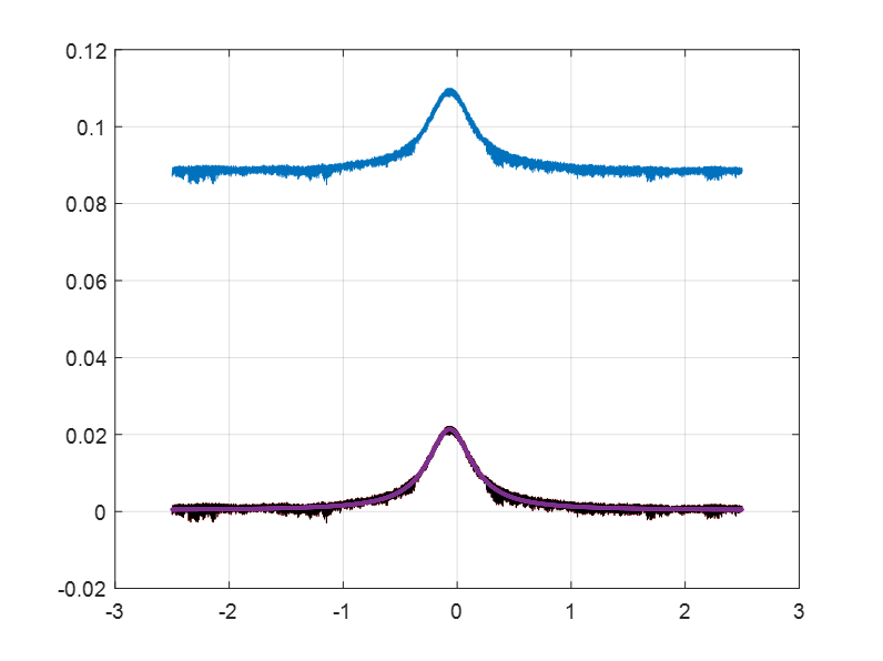
Xinyi Lu | Fixed | info | lasers and optics | Optical room | Install new mirrors | - Today, Ronic and I changed the signal generator to a low-noise one (with a delay time of only 0.5 us). Then we moved the D-shaped mirrors, optimized the alignment and locking. We re-measured the finesse and it is 16,760. It improves but not much.
- Tomorrow, we will clean the environment, open the cavity, and use UV light to see if there is any dust on the surface of the mirrors.
| Xinyi Lu wrote: |
|
- In the last two days, Ronic and I installed new mirrors after cleaning the environment, and locked the cavity.
- We added an AOM to feedback on the high-frequency noise, but the locking condition was still not good enough. We found out that the signal generator available for this AOM has a long delay time (3 us), which may lead to low feedback bandwidth. So tomorrow we will use another AOM and signal generator to optimize the locking.
- Under this not good enough locking, we measured the finesse. Unfortunately, the finesse was measured as 15,478, which is much lower than the expected 42,000. It means that about 260ppm of additional loss was introduced. We will measure the finesse again after optimizing the locking and coupling.
By the way, attached are the delay time results for phase modulation of different signal generators:
- RIGOL DG4162: 0.7 us (best)
- SIGLENT SDG6022X: 3 us
- SIGLENT SDG7032A: 2.9 us
|
|
| Attachment 1: New_finesse.png
|  |
|
183
|
Thu Jan 18 22:14:03 2024 |
Xinyi Lu | Fixed | info | lasers and optics | Optical room | Install new mirrors | - In the last two days, Ronic and I installed new mirrors after cleaning the environment, and locked the cavity.
- We added an AOM to feedback on the high-frequency noise, but the locking condition was still not good enough. We found out that the signal generator available for this AOM has a long delay time (3 us), which may lead to low feedback bandwidth. So tomorrow we will use another AOM and signal generator to optimize the locking.
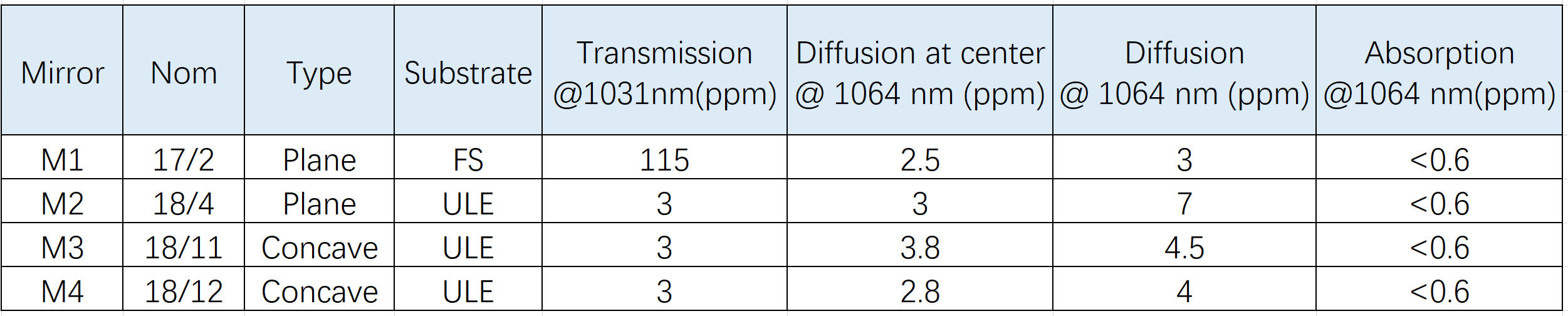
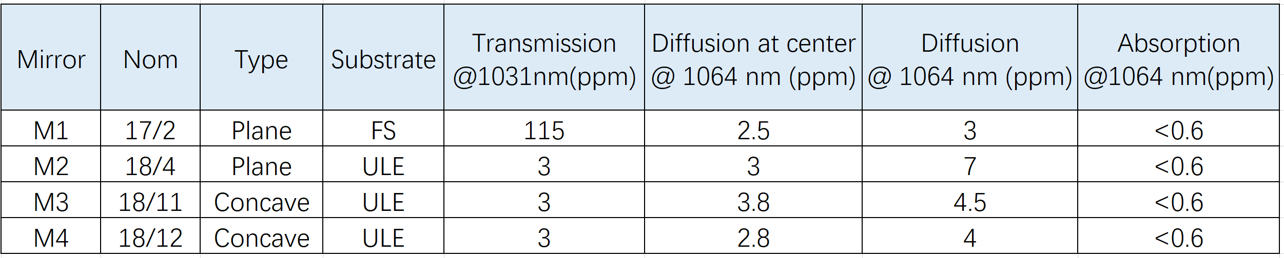
- Under this not good enough locking, we measured the finesse. Unfortunately, the finesse was measured as 15,478, which is much lower than the expected 42,000. It means that about 260ppm of additional loss was introduced. We will measure the finesse again after optimizing the locking and coupling.
By the way, attached are the delay time results for phase modulation of different signal generators:
- RIGOL DG4162: 0.7 us (best)
- SIGLENT SDG6022X: 3 us
- SIGLENT SDG7032A: 2.9 us |
| Attachment 1: New_mirrors.png
|  |
| Attachment 2: finesse.png
|  |
| Attachment 3: locking.jpg
|  |
|
182
|
Wed Jan 17 21:11:59 2024 |
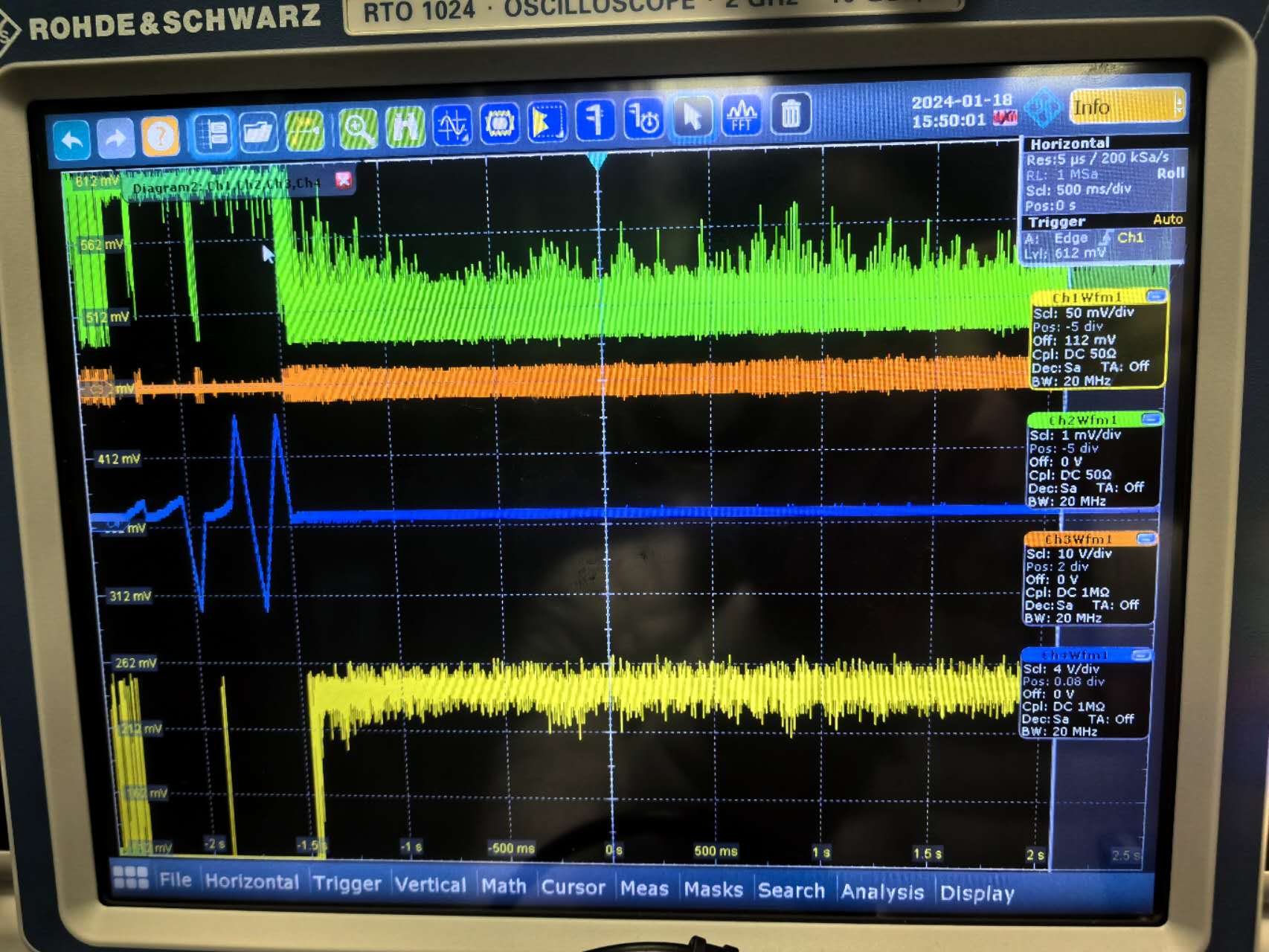
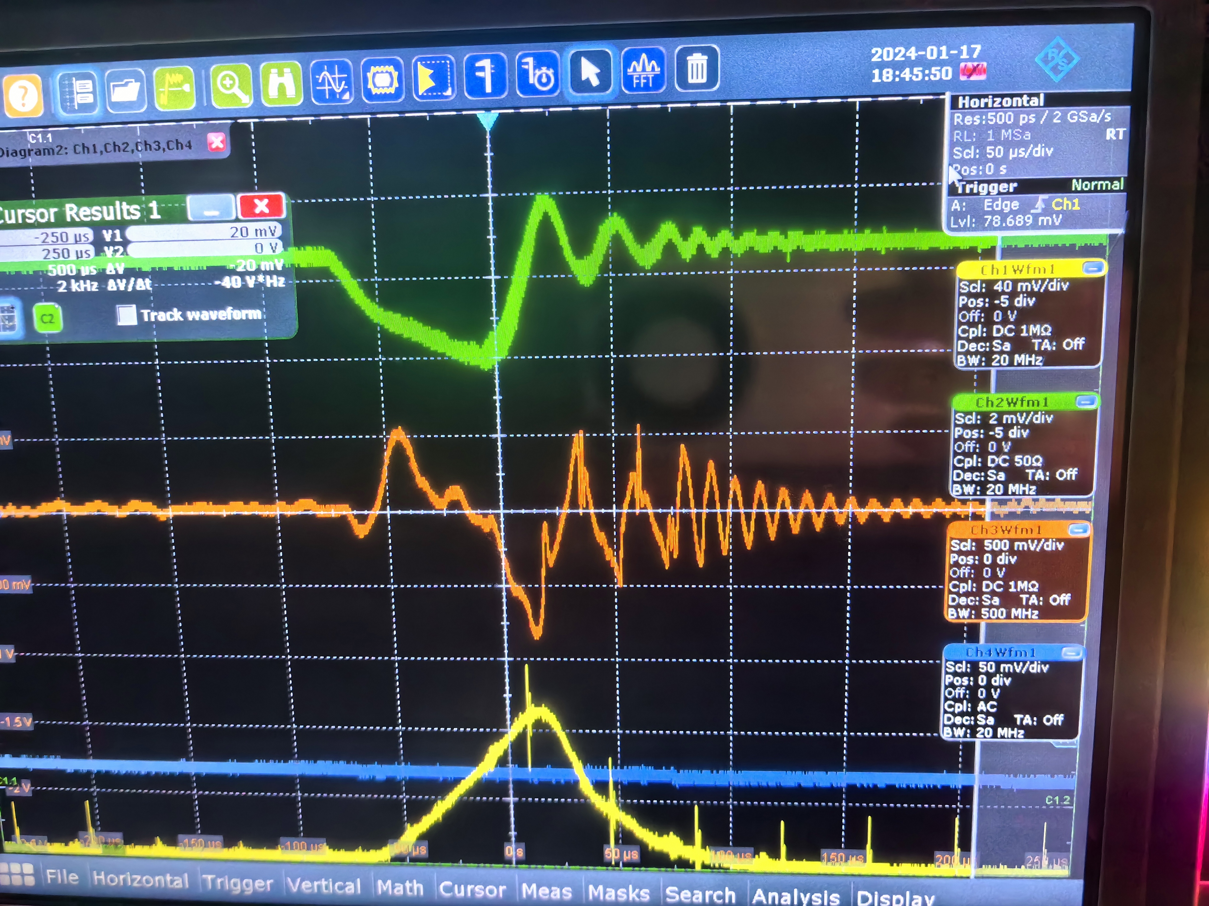
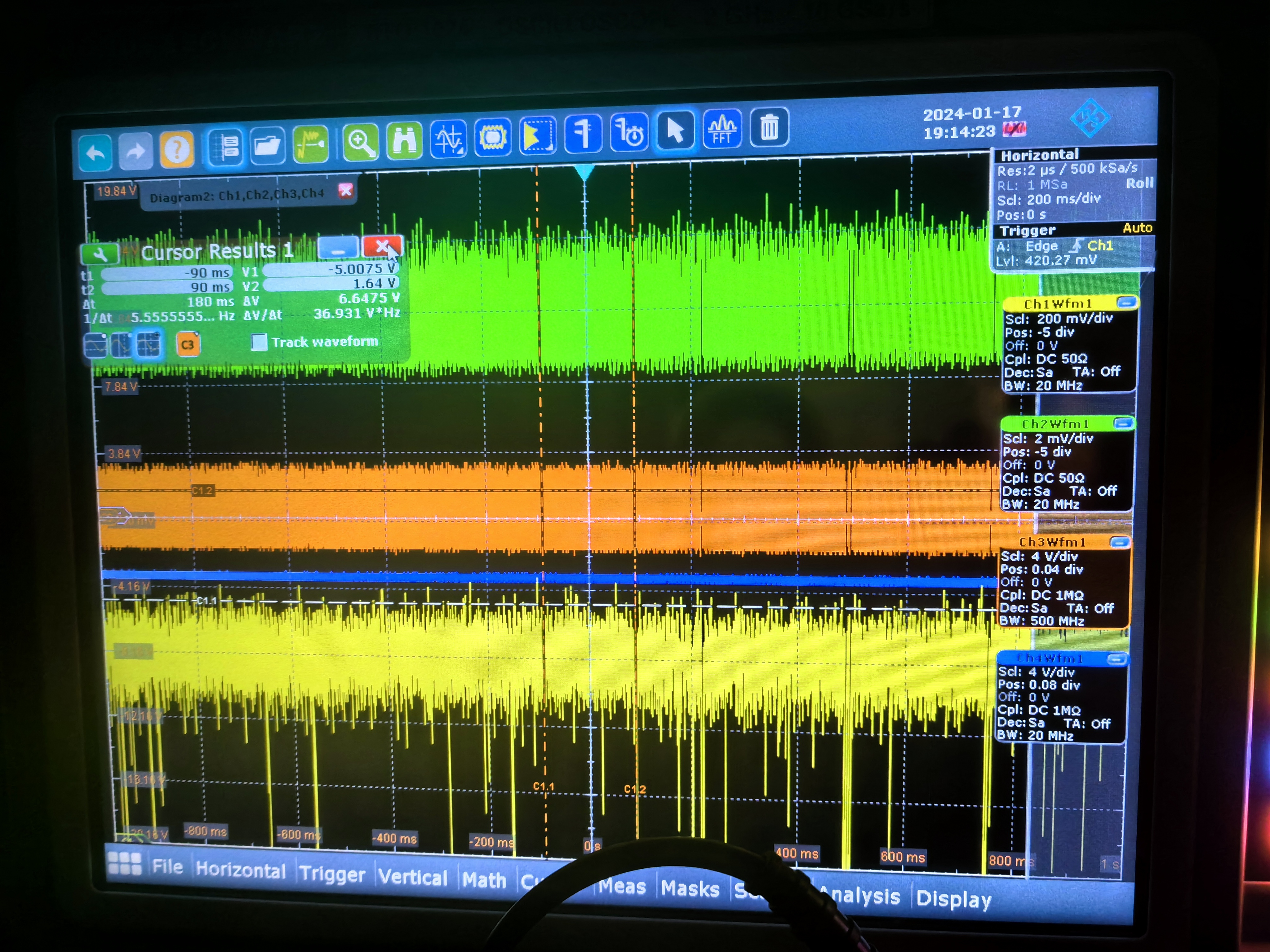
Xinyi Lu | Fixed | info | lasers and optics | Optical room | Install new mirrors | Today, Ronic and I installed the new mirrors and got resonance. We can see the oscillations in this high-finesse case. We haven't carefully optimized the alignment. Coupling efficiency is about 15% and the cavity can be locked.
Tomorrow we will optimize the alignment and locking, and measure the finesse. |
| Attachment 1: New_mirrors.png
|  |
| Attachment 2: oscillations.jpg
|  |
| Attachment 3: locking.jpg
|  |
|
181
|
Tue Jan 16 18:42:42 2024 |
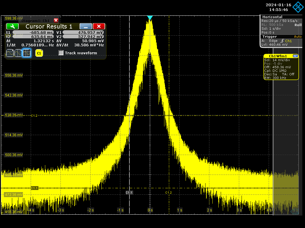
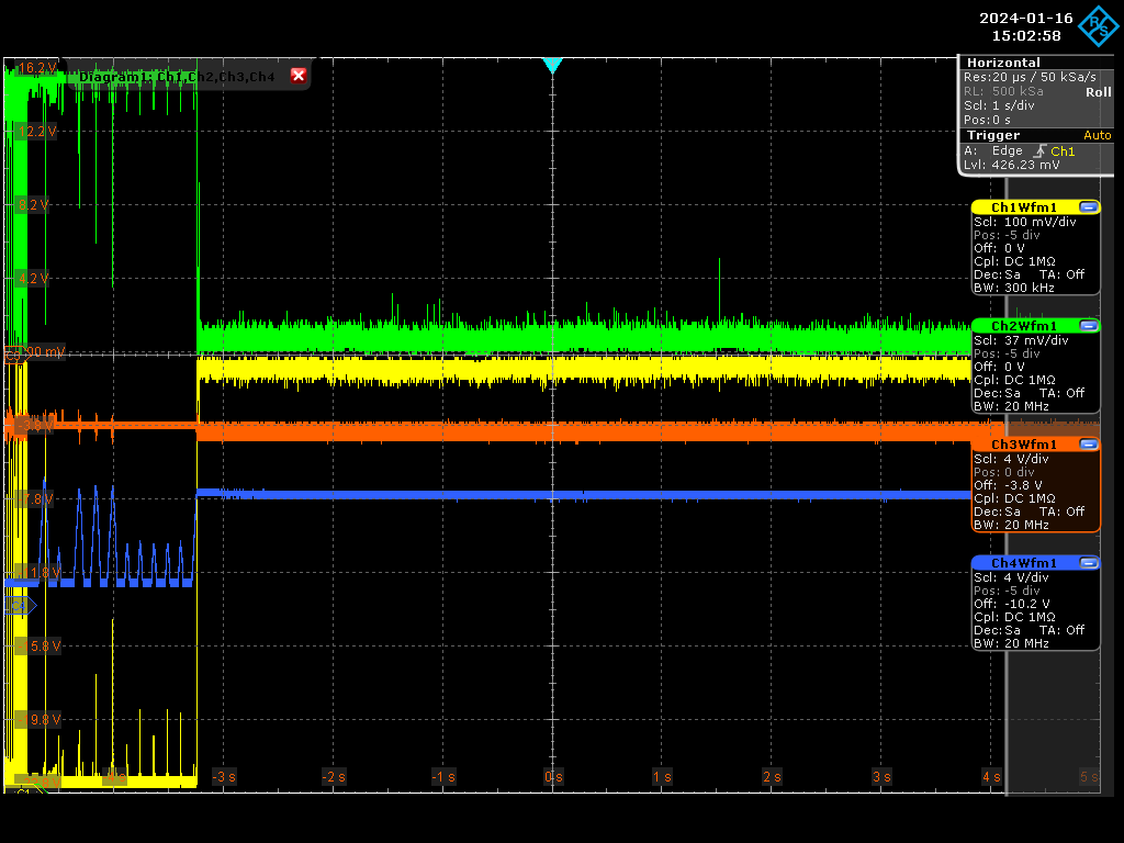
Xinyi Lu | Fixed | info | lasers and optics | Optical room | FSR and Finesse measurement | - Today, Ronic and I measured the finesse and FSR after optimizing the locking. FSR was adjusted to 160.27 MHz to match the pulsed laser repetition rate. The finesse was 3029.
Note: It's now CW laser injected, SBOX's old mirrors. There are lots of dust on the old mirrors without cleaning.
- Then we cleaned the cavity inside and outside, and removed four mirrors.
- Tomorrow we will check the clean condition and install new mirrors if we can. Before installation, it may be helpful to discuss how to minimize the introduction of dust. |
| Attachment 1: Screenshot_2024-01-16_2_145546.png
|  |
| Attachment 2: Screenshot_2024-01-16_4_150258.png
|  |
|
180
|
Mon Jan 15 19:19:00 2024 |
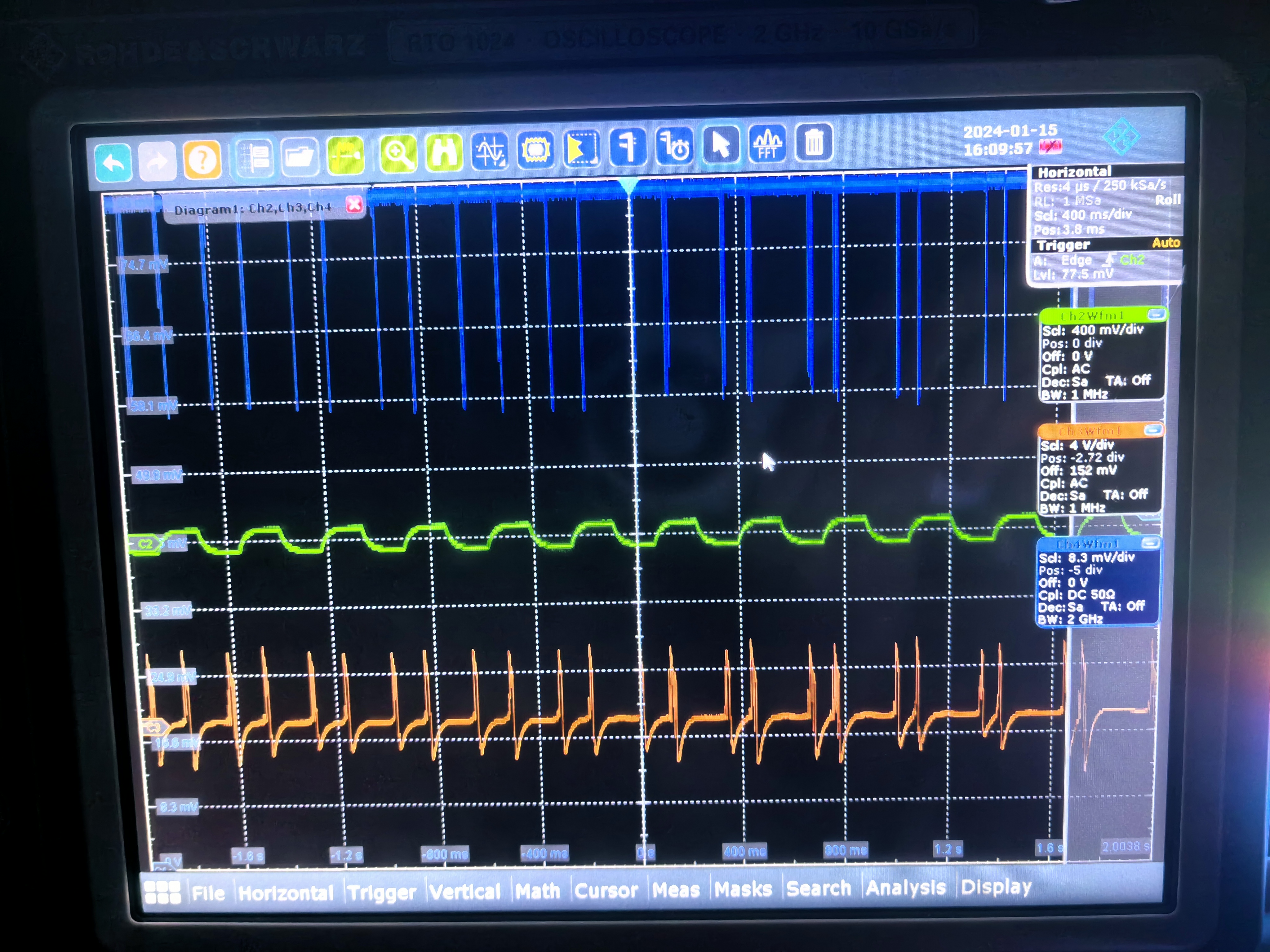
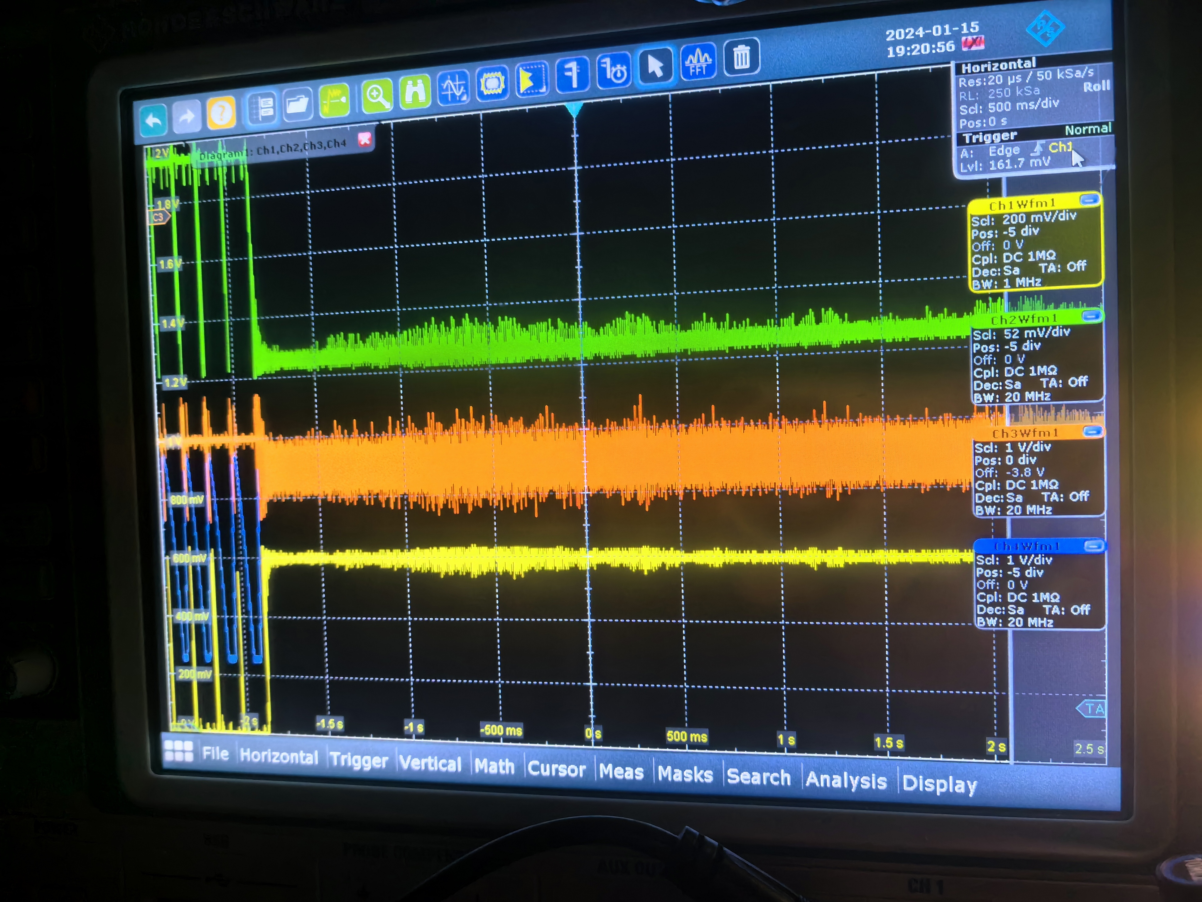
Xinyi Lu | Fixed | info | lasers and optics | Optical room | Coupling efficiency improvement | - We got 30% coupling efficiency by installing a set of telescopes, adjusting the polarization and optimizing the alignment. The diameter of the cavity mode is about 2.1mm.
- Ronic and I successfully locked the optical cavity. Tomorrow we will test the FSR and finesse.
| Xinyi Lu wrote: |
|
- Recently we have focused on improving the coupling efficiency. Without the telescope, the original coupling efficiency was less than 3%.
- I measured the parameters of the incident CW laser using both a HASO wavefront sensor and a CCD. I designed and installed the telescope, but the coupling efficiency still did not improve.
- After discussing with Aurélien and Ronic, it was decided to replace the M1 because the original M1 has a damaged spot in the center to the left. The damaged spot may be causing the coupling efficiency to be too low.
- Today, I replaced the M1 and realigned the cavity. Fortunately, the coupling efficiency has improved.
- We'll continue to optimize the alignment, improve the coupling, and carry out tests on the cavity.
|
|
| Attachment 1: coupling_efficiency.jpg
|  |
| Attachment 2: cavity_locking.jpg
|  |
|
179
|
Wed Jan 10 18:35:46 2024 |
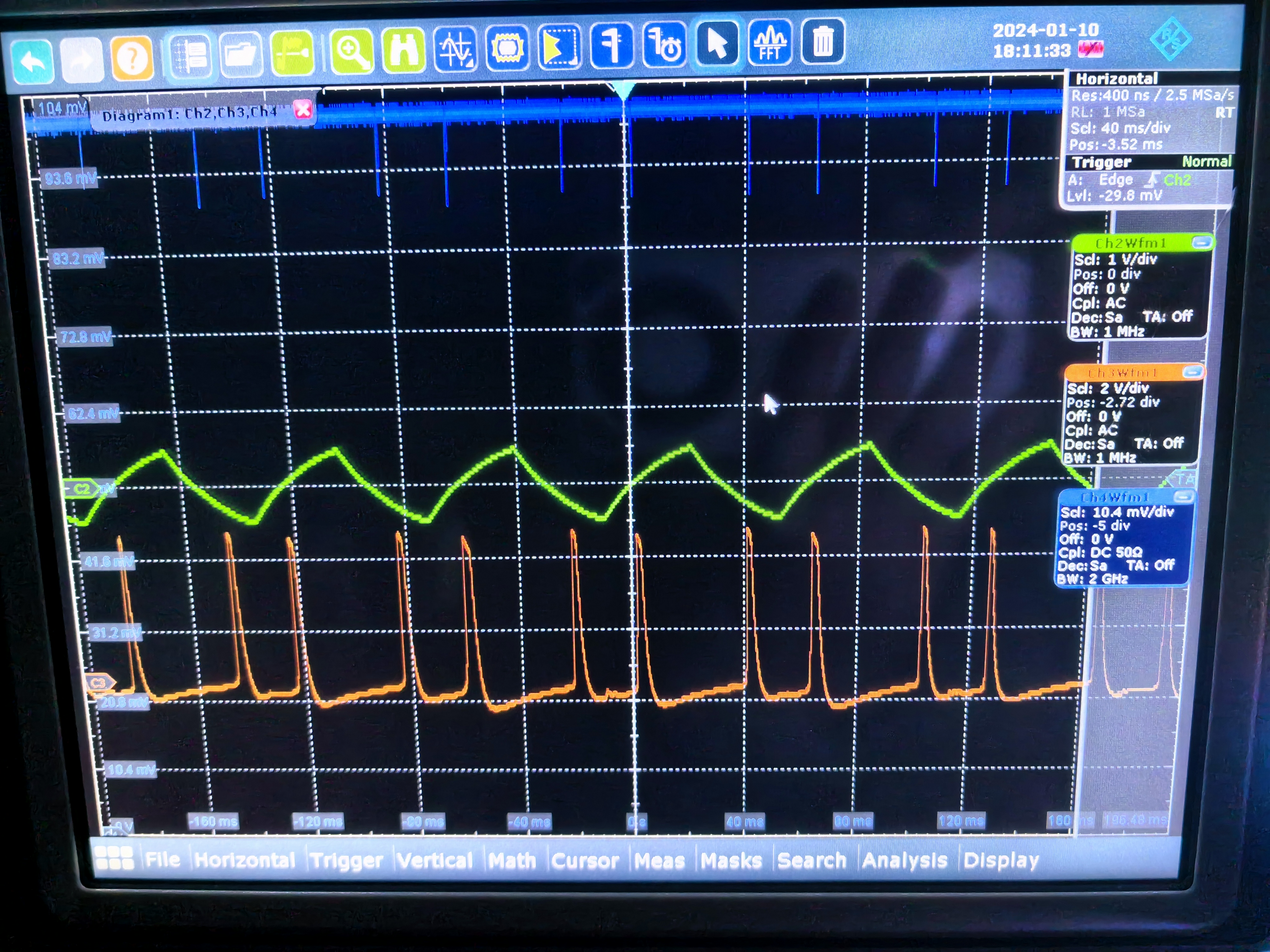
Xinyi Lu | Fixed | info | lasers and optics | Optical room | Coupling efficiency improvement | - Recently we have focused on improving the coupling efficiency. Without the telescope, the original coupling efficiency was less than 3%.
- I measured the parameters of the incident CW laser using both a HASO wavefront sensor and a CCD. I designed and installed the telescope, but the coupling efficiency still did not improve.
- After discussing with Aurélien and Ronic, it was decided to replace the M1 because the original M1 has a damaged spot in the center to the left. The damaged spot may be causing the coupling efficiency to be too low.
- Today, I replaced the M1 and realigned the cavity. Fortunately, the coupling efficiency has improved.
- We'll continue to optimize the alignment, improve the coupling, and carry out tests on the cavity. |
| Attachment 1: Coupling_efficiency_0110.jpg
|  |
| Attachment 2: damaged_spot_on_M1.png
|  |
|
178
|
Wed Dec 20 10:45:37 2023 |
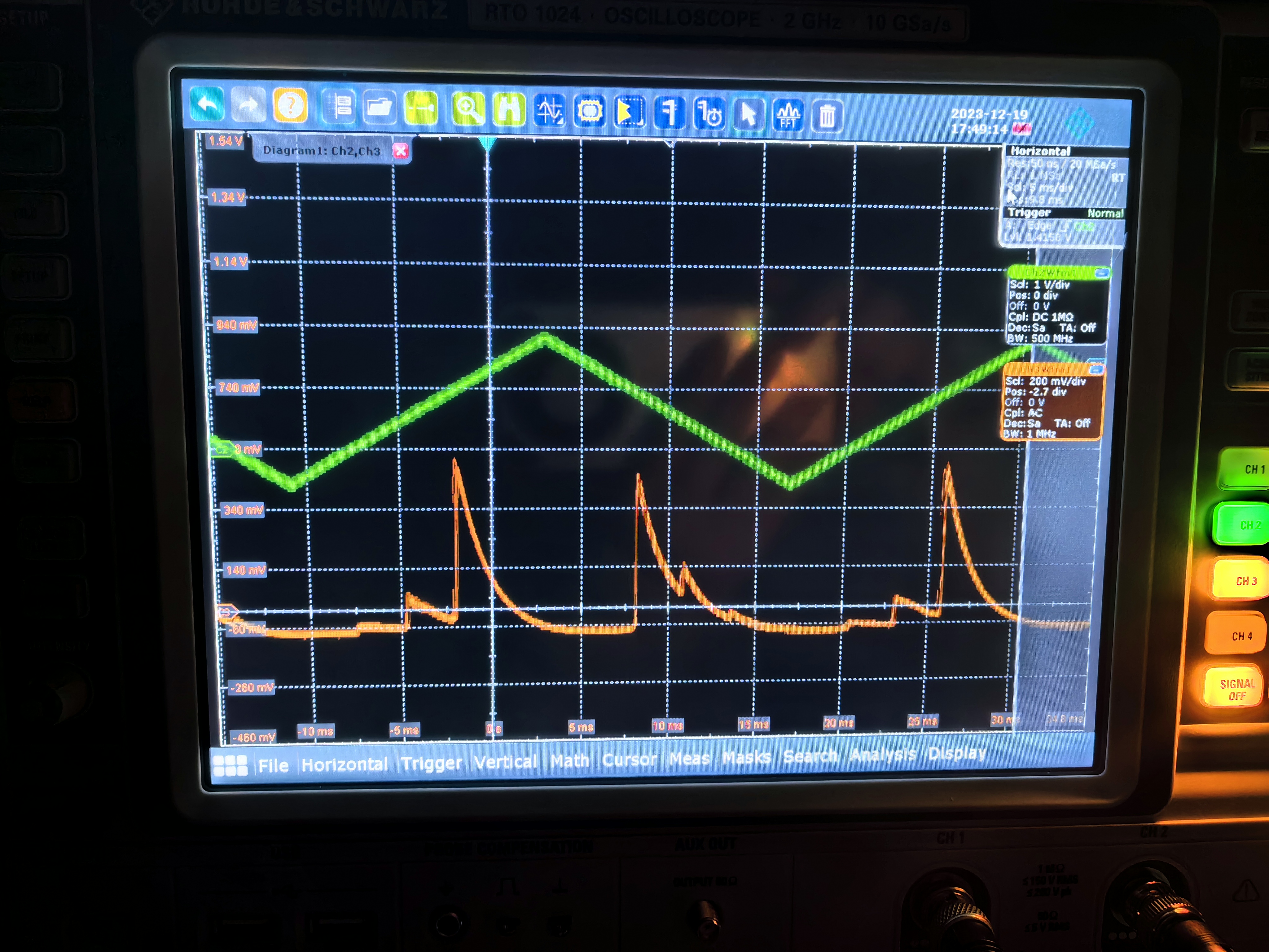
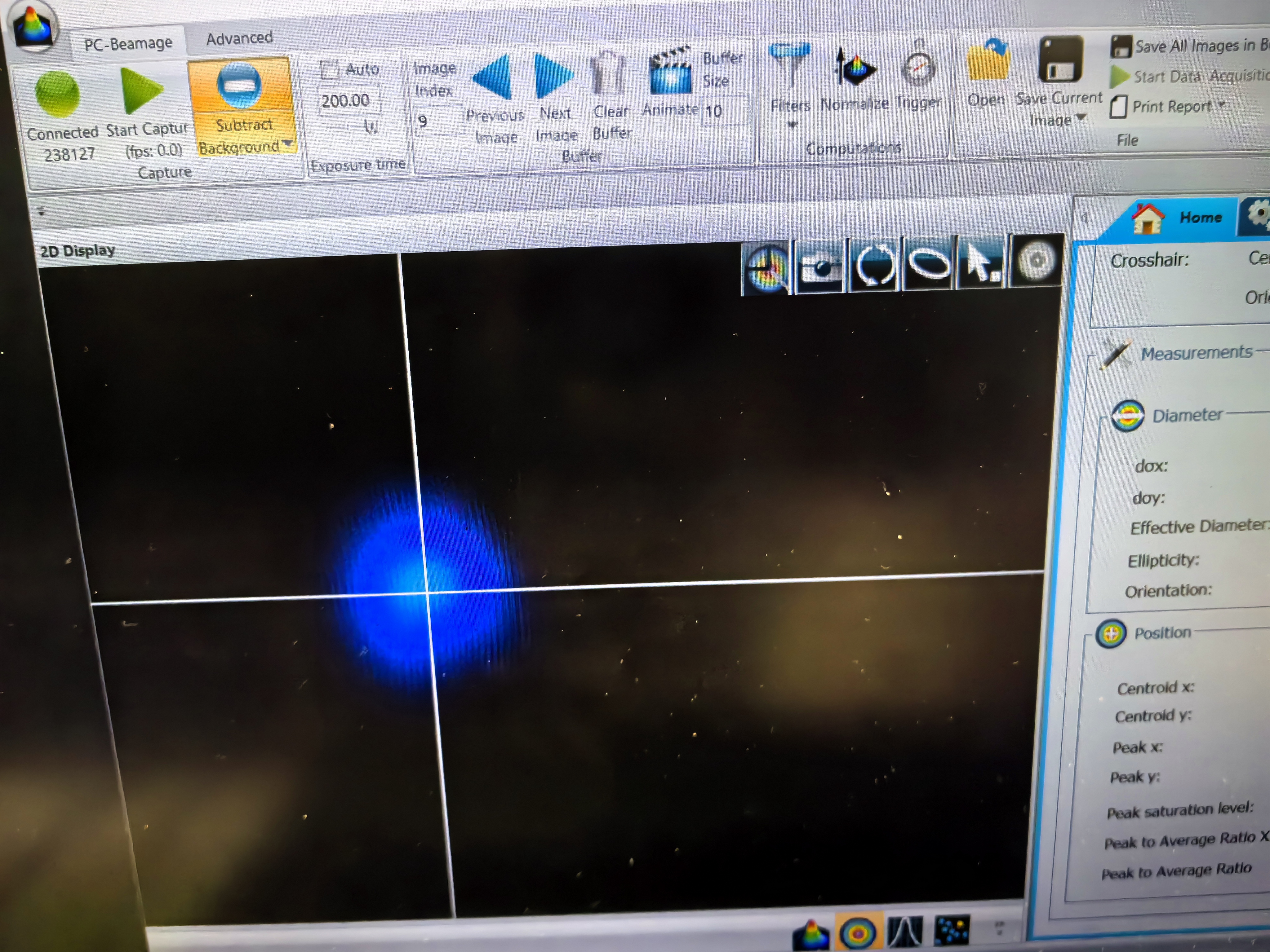
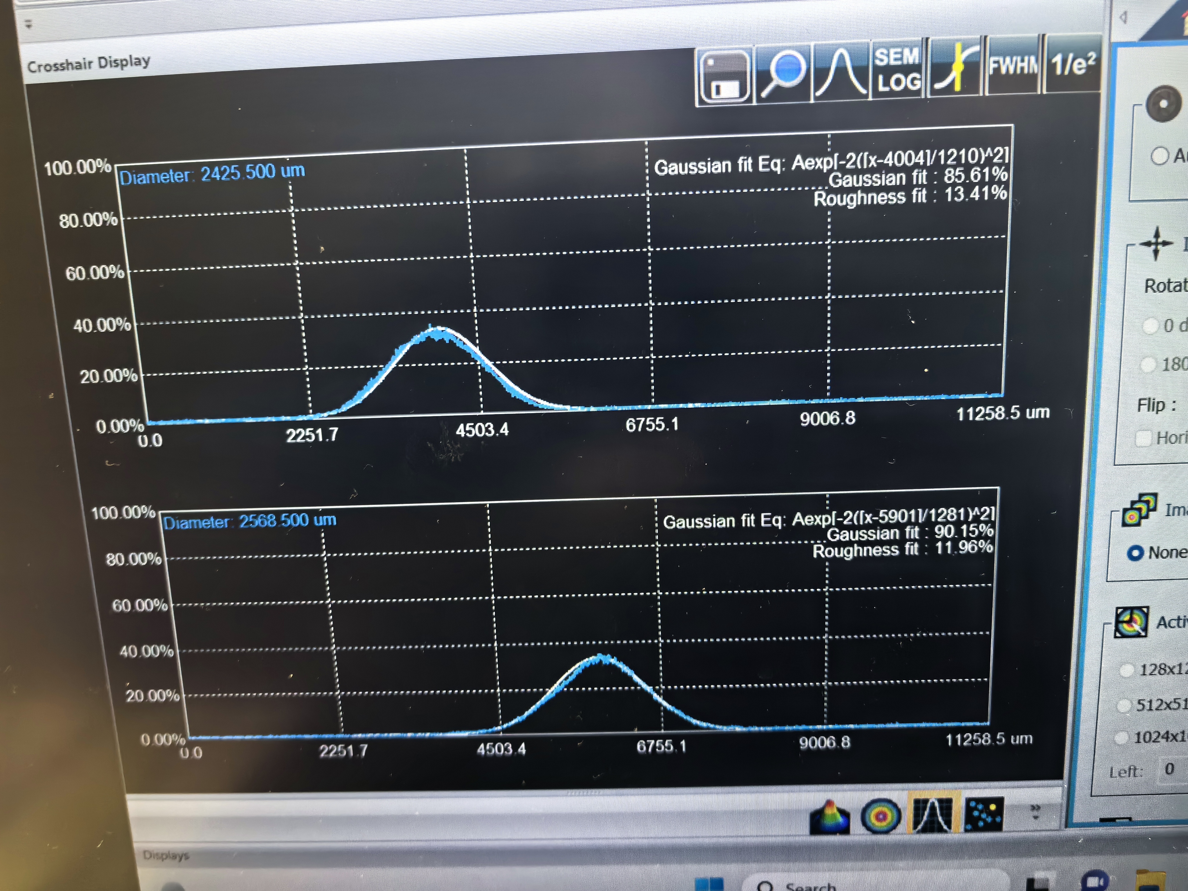
Xinyi Lu | Fixed | report | lasers and optics | Optical room | Mounts installation and cavity alignment | - Over the last few days, Viktor, Ronic and I have reinstalled the mounts and realigned the cavity with CW laser and old mirrors. By optimizing the injector mirrors, we got the fundamental mode at the transmission. We measured the beam size in the M2 window with a diameter of 2.5 mm.
- The current coupling efficiency is low. There is a need to increase the coupling in order to lock the cavity and measure FSR and finesse.
- The next step is to measure the incident light parameters and design the telescope to improve the coupling efficiency.
| Xinyi Lu wrote: |
|
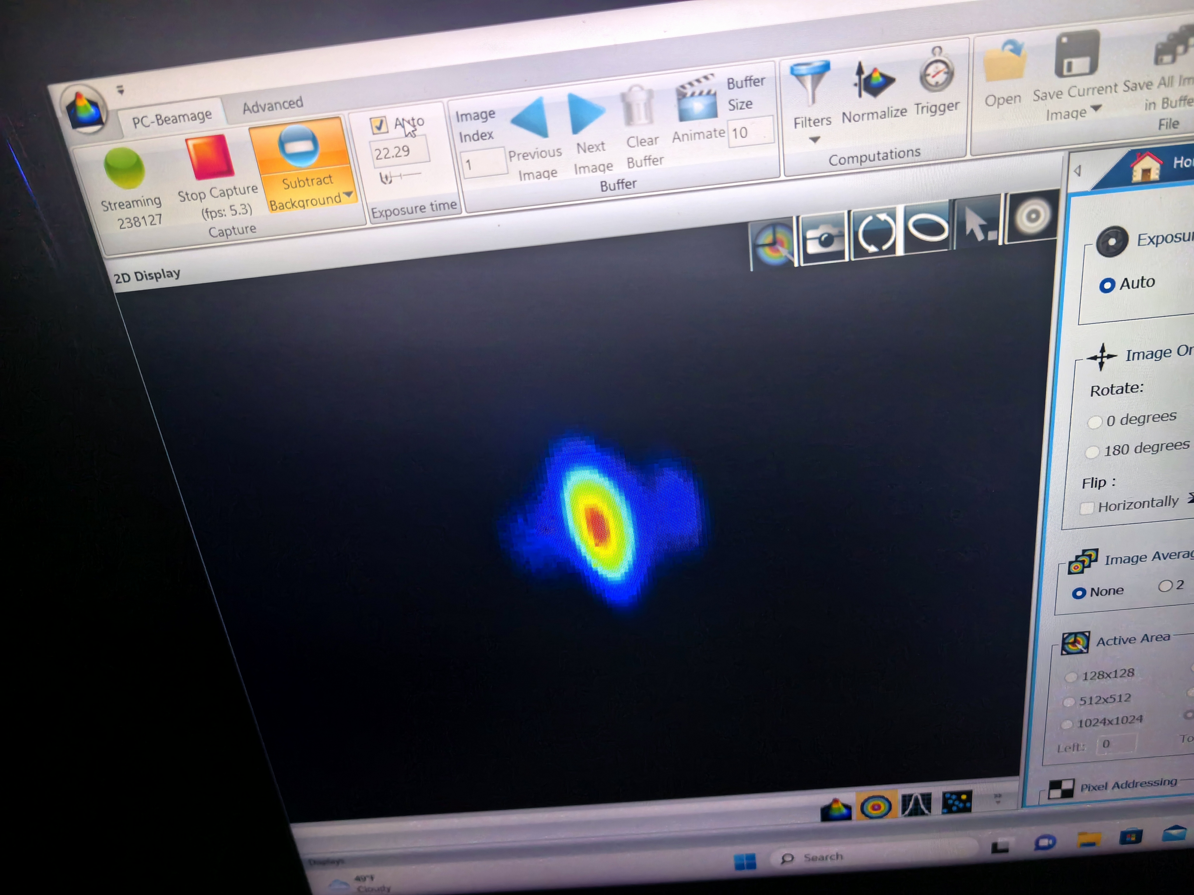
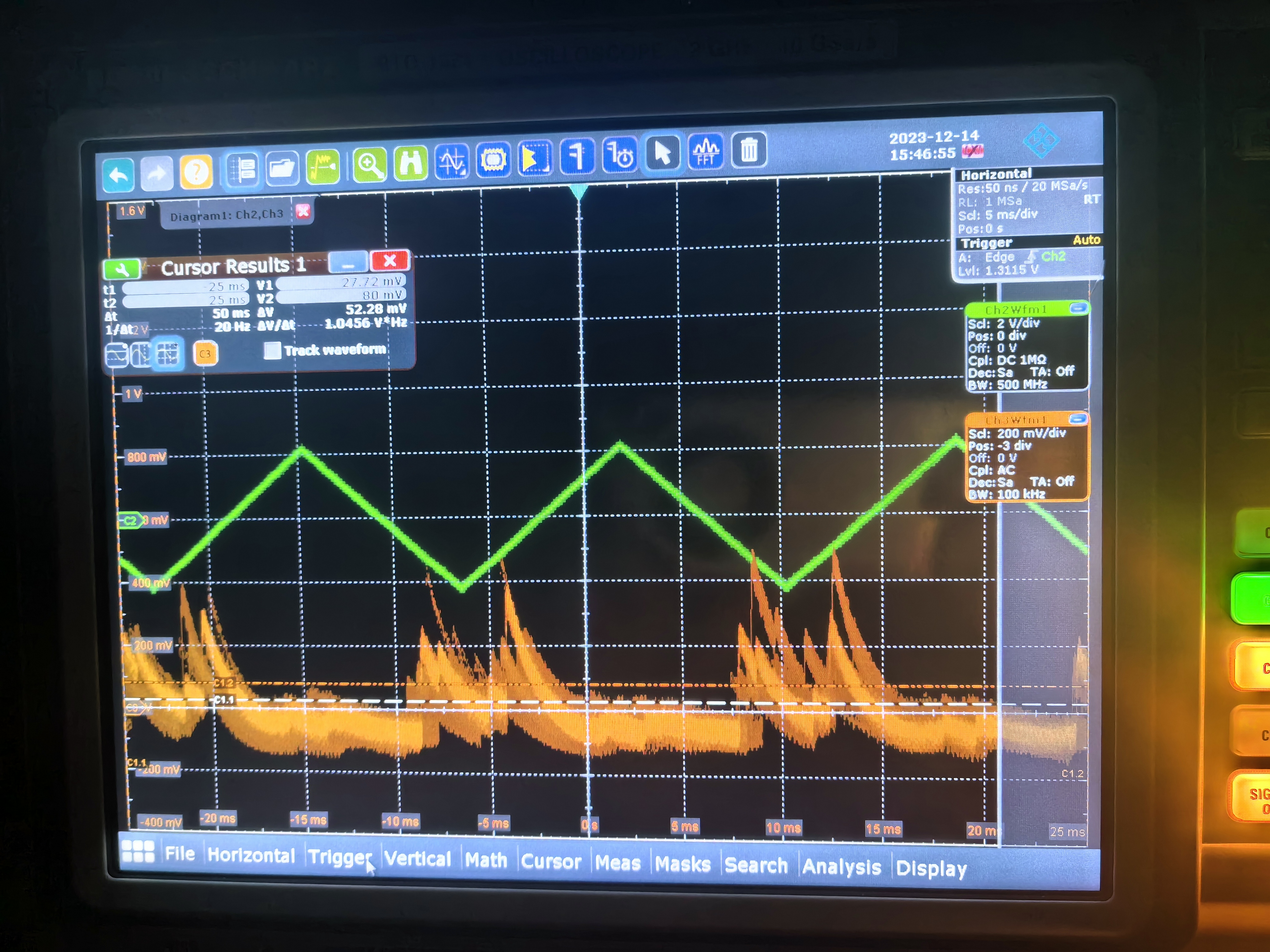
Over the past few days, Viktor, Ronic and I have continued to align the cavity. We installed 4 mirrors and monitored the transmitted laser with a CCD and photodiode. By adjusting the motors of the cavity mirror stages and the injector mirrors, we obtained resonances and less symmetric TEM20-like patterns. Possible reasons for this are a mismatch between the beam sizes of the laser and the cavity mode, and the mounts are installed in rough positions.
Tomorrow, we plan to use the CW laser to realign the optical cavity and position the mounts more precisely.
| Xinyi Lu wrote: |
|
Over the last two days, Viktor, Ronic and I have started to install the mirror mounts and try to align the cavity.
- We used the Menhir laser @ 160MHz for alignment.
- To make it easier to operate, we removed some lenses and waveplates, and kept only a few necessary reflective mirrors.
- We measured the distance with rulers and placed the mounts in designed positions.
- We installed Iris on the mirror mounts, used a CCD camera to determine if the beam was in the center, and optimized the two reflective mirrors outside the cavity.
- There were some problems with the controller of the injection mirrors (Newport™) in front of the cavity, and Ronic has fixed them successfully.
- Next week, we will continue to align the cavity, measure the cavity mode, and design the telescope. We will install the old SBX mirrors for alignment first, and then replace them with the final good mirrors.
|
|
|
| Attachment 1: resonances.jpg
|  |
| Attachment 2: cavity_mode.jpg
|  |
| Attachment 3: cavity_mode_diameter.jpg
|  |
|
177
|
Thu Dec 14 17:52:53 2023 |
Xinyi Lu | Fixed | report | lasers and optics | Optical room | Mounts installation and cavity alignment | Over the past few days, Viktor, Ronic and I have continued to align the cavity. We installed 4 mirrors and monitored the transmitted laser with a CCD and photodiode. By adjusting the motors of the cavity mirror stages and the injector mirrors, we obtained resonances and less symmetric TEM20-like patterns. Possible reasons for this are a mismatch between the beam sizes of the laser and the cavity mode, and the mounts are installed in rough positions.
Tomorrow, we plan to use the CW laser to realign the optical cavity and position the mounts more precisely.
| Xinyi Lu wrote: |
|
Over the last two days, Viktor, Ronic and I have started to install the mirror mounts and try to align the cavity.
- We used the Menhir laser @ 160MHz for alignment.
- To make it easier to operate, we removed some lenses and waveplates, and kept only a few necessary reflective mirrors.
- We measured the distance with rulers and placed the mounts in designed positions.
- We installed Iris on the mirror mounts, used a CCD camera to determine if the beam was in the center, and optimized the two reflective mirrors outside the cavity.
- There were some problems with the controller of the injection mirrors (Newport™) in front of the cavity, and Ronic has fixed them successfully.
- Next week, we will continue to align the cavity, measure the cavity mode, and design the telescope. We will install the old SBX mirrors for alignment first, and then replace them with the final good mirrors.
|
|
| Attachment 1: CCD.jpg
|  |
| Attachment 2: oscillograph.jpg
|  |
|
176
|
Fri Dec 8 18:59:24 2023 |
Xinyi Lu | Fixed | report | lasers and optics | Optical room | Mounts installation and cavity alignment | Over the last two days, Viktor, Ronic and I have started to install the mirror mounts and try to align the cavity.
- We used the Menhir laser @ 160MHz for alignment.
- To make it easier to operate, we removed some lenses and waveplates, and kept only a few necessary reflective mirrors.
- We measured the distance with rulers and placed the mounts in designed positions.
- We installed Iris on the mirror mounts, used a CCD camera to determine if the beam was in the center, and optimized the two reflective mirrors outside the cavity.
- There were some problems with the controller of the injection mirrors (Newport™) in front of the cavity, and Ronic has fixed them successfully.
- Next week, we will continue to align the cavity, measure the cavity mode, and design the telescope. We will install the old SBX mirrors for alignment first, and then replace them with the final good mirrors. |
|
175
|
Thu Dec 7 09:30:03 2023 |
Ronic Chiche | Fixed | info | mechanics | lasers and optics | detectors and electronics | software | Optical room | new setup for the 160MHz Menhir oscillator | from the begining of the week, Xinyi, Aurélien, Viktor and myself started to install a new setup for the Menhir 160MHz oscillator.
the goal is to rich a record power in the FP-cavity.
- the 160MHz Menhir oscillator has been injected in a fiber.
we reached ~ 25mV on 50ohms which is equivalent to 0.5mA in a DET10 photodiode.
=> ~1mW coupled in the fiber => it is not enough to put an EOM and an AOM before the amplifier.
=> one needs to improve the fiber injection.
in fact, I checked the power in the fiber with a powermeter, and it is ~16mW !
at this level of power, one needs to add some optical density before connecting to a photodiode, or it can be saturated.
- we calculated the mirrors position in the SBOX vessel to obtain a 160MHz FSR FP-cavity.
see in attached files, the calculations and scheme in the PPTX file and the Matlab code to get some results.
- we cleaned the optical table and verified with the dust counter that the SBOX environnement is clean.
the 2nd airflow box (from the entrance) seems more dusty (measureed directly close to the top) than the others.
we also opened the vessel and cleaned it.
see the dust measurement inside the SBOX.
- we checked the motors inside the vessel :
=> spherical and plan mirrors translation stage control with the ESP300.
the translation stage have been placed on the middle of their range.
=> the 2 D-shape mirrors translation stage control with PICOMOTORS controller Newport 8742.
- today, Viktor and Xinyi should start the installation of the mirrors mount and make some test to check if the beam is properly propagated inside the FP-cavity, before installing the final mirrors.
the mirror mounts are the Newport SU100TW-F2K zero-drift low waveform distortion : https://www.newport.com/p/SU100TW-F2K
they can accept mirrors with 6-6.35mm thickness => normally the SBOX mirrors from the LMA have a 6.35mm thickness.
see 1st file from this post : https://elog.lal.in2p3.fr/FPC/SBOX+commissioning/174 |
| Attachment 1: Plan_SBOX_@_160MHz.pptx
|
| Attachment 2: Implantation_disymmetric.m
|
clear
clc

% simulation parameters
c=299792458;            % light speed in vacuum
Frep=160.3084e6;        % laser repetition rate
D=0.07;                 % side distance between "output" windows of the vessel
DR=0.12;                % side distance between "input" windows of the vessel
L0=1.02;                % cavity box length
L3=0.505;               % distance between spherical mirrors

theta1=linspace(0.115,0.120,1e3);

% calculated parameters
Lrt=c/Frep;
theta2=2*atan(1./((Lrt/D)-1./tan(theta1/2)));
L2=D./sin(theta2);
L4=D./sin(theta1);
L1=Lrt-L2-L3-L4;

LM3=(DR-D)./tan(theta2);
LM2=L0-DR./tan(theta2);
LM1=L0-L1-LM2;
LM4=L0-L3-LM3;

id=LM1>0.15 & LM2>0.15 & LM3>0.15 & LM4>0.15 & abs(LM1-LM3)>0.08 & abs(LM2-LM4)>0.08;
L1(~id)=0;
L2(~id)=0;
L4(~id)=0;
LM1(~id)=0;
LM2(~id)=0;
LM3(~id)=0;
LM4(~id)=0;

figure(1)
clf
plot(theta1*1e3,L1)
hold on
plot(theta1*1e3,L2)
plot(theta1*1e3,L4)
plot(theta1*1e3,LM1)
plot(theta1*1e3,LM2)
plot(theta1*1e3,LM3)
plot(theta1*1e3,LM4)
grid on
legend('L1','L2','L4','LM1','LM2','LM3','LM4','location','best')
xlabel('theta1 angle (mrad)')
ylabel('length parameters (m)')

id=find(id~=0);
id=id(1);

disp(['LRT = ' num2str(Lrt) ' m'])
disp(['D = ' num2str(D*1e3) ' mm'])
disp(['theta1 = ' num2str(theta1(id)*1e3) ' mrad'])
disp(['theta2 = ' num2str(theta2(id)*1e3) ' mrad'])
disp(['L1 = ' num2str(L1(id)*1e3) ' mm'])
disp(['L2 = ' num2str(L2(id)*1e3) ' mm'])
disp(['L3 = ' num2str(L3*1e3) ' mm'])
disp(['L4 = ' num2str(L4(id)*1e3) ' mm'])
disp(' ')
disp(['L0 = ' num2str(L0) ' m'])
disp(['DR = ' num2str(DR*1e3) ' mm'])
disp(['LM1 = ' num2str(LM1(id)*1e3) ' mm'])
disp(['LM2 = ' num2str(LM2(id)*1e3) ' mm'])
disp(['LM3 = ' num2str(LM3(id)*1e3) ' mm'])
disp(['LM4 = ' num2str(LM4(id)*1e3) ' mm'])
disp(['LM3-LM1 = ' num2str((LM3(id)-LM1(id))*1e3) ' mm'])
disp(['LM2-LM4 = ' num2str((LM2(id)-LM4(id))*1e3) ' mm'])
|
| Attachment 3: IMG_20210519_155329.jpg
|  |
|
174
|
Thu Dec 7 09:09:27 2023 |
Ronic Chiche | Fixed | info | lasers and optics | ThomX igloo | New mirrors batch informations | the 2 files describe the specfications for the 16 mirrors ordered (4 for ThomX + spare, 4 for SBOX + spare) and the measurements made by the LMA.
I add also a 3rd file in which all the "special' mirrors are referenced. |
| Attachment 1: miroirs_puma_2022_thomx_Kbox.docx
|
| Attachment 2: Miroirs_à_1031_nm-ThomX_-_KBox_Mars_2023.pdf
|
| Attachment 3: Recap_miroirs_KBOX_et_THOMX.xlsx
|
|
173
|
Fri Jan 6 12:33:18 2023 |
Ronic Chiche | Fixed | info | lasers and optics | Optical room | Laser Menhir reinstallation + CVBG + fiber injection | The lab purchased the Menhir laser @ 216MHz.
it has been sent back to Menhir photonics for inspection, and then is now at lab.
it has been reinstalled to the SBOX setup with injection in a CVBG for pulse stretching before amplification.
the power after CVBG is 24mV.
the power coupled to the fiber is only 6.4mW => to be optimized.
the spectrum has been mesured after CVBG and seems correct : picture is attached.
|
| Attachment 1: MenhirJan2022.PNG
|  |
|