| ID |
Date |
Author |
Status |
Type |
Category |
Location |
Title |
|
198
|
Tue Mar 12 22:13:47 2024 |
Xinyi Lu | Fixed | info | lasers and optics | Optical room | Coupling efficiency improvement |
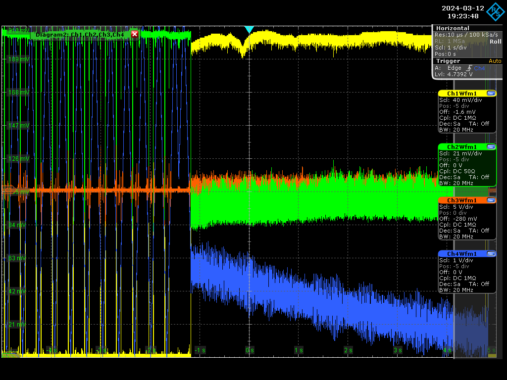
- Today, Ronic and I locked at the amplifier current of 2 A and obtained ~60% coupling after optimizing the CEP (see Figure 1).
- The injected power is 10 W at 2 A. We measured only 14 kW inside the cavity, which corresponds to an effective gain of 1,400 and a full gain of 2,300. The cavity finesse is 23,000 and the normal gain should be around 6,200.
- We found fluctuations in transmission, possibly because of mode degradation. Tomorrow we will use D-shape mirrors to suppress high-order modes and optimize alignment and locking.
| Xinyi Lu wrote: |
|
Today, Ronic and I installed the new telescope and locked the cavity.
- We locked at the amplifier current of 1 A and obtained 32% of coupling. (see Figure 1)
- The telescope was designed for a current of 2 A (output power ~10 W). To inject this power, we need to add some filters to devices.
- For CEP tuning, when we changed the AOM frequency while cavity locking, sometimes it caused unlock and power drops. It will be dangerous in high-power cases. So it's better to optimize the AOM frequency in low power and just tune the laser current in high power. Now the current variation range of the menhir laser is 750mA to 950mA.
| Xinyi Lu wrote: |
|
- These days, Ronic, Fatematuj and I measured the beam parameters of the output of the third-stage amplifier.
- We used 2 wedges and reflection filters to reduce the intensity on the CCD.
- We measured multiple points at pump current of 2 A (output power ~10 W). The waist diameter of the output is w_x = 792.26 um, w_y=873.90 um.
- The next step is to design the telescope and improve the coupling efficiency.
|
|
|
| Attachment 1: Screenshot_2024-03-12_0_192348.png
|
 |
|
186
|
Fri Jan 26 17:33:05 2024 |
Xinyi Lu | Fixed | info | lasers and optics | Optical room | Cleaning of Mirrors |
Today Daniele, Ronic and I cleaned the mirrors and locked the cavity. However, the finesse was only 13,000 because of the not clean enough environment and not pure enough alcohol and water.
We will carefully clean the environment, clean the mirrors again with pure alcohol and water and measure the finesse when I return. If it doesn't work, we will use plasma to clean the mirror. We have gone to the lab to confirm the plasma device and then we will study the best parameter settings: polarity, time, and current.
Have a nice weekend! |
|
187
|
Mon Feb 12 17:17:04 2024 |
Xinyi Lu | Fixed | info | lasers and optics | Optical room | Cleaning of Mirrors |
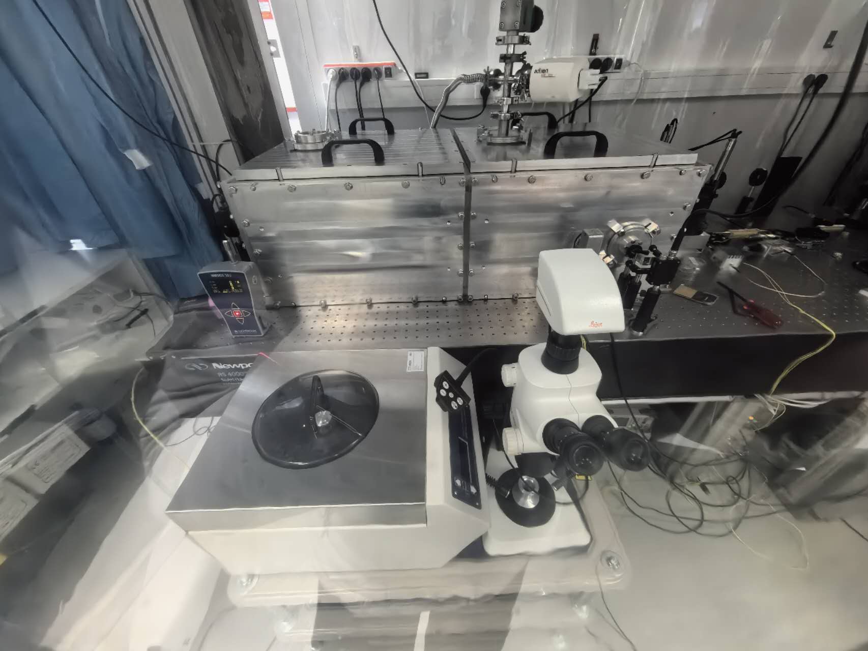
- Today we cleaned the environment and put the spin coater and microscope inside the airflow.
- Tomorrow, Daniele and I will clean the mirrors one by one using pure alcohol and water, and measure the finesse each time. If it does not improve, we will clean them with plasma.
| Xinyi Lu wrote: |
|
Today Daniele, Ronic and I cleaned the mirrors and locked the cavity. However, the finesse was only 13,000 because of the not clean enough environment and not pure enough alcohol and water.
We will carefully clean the environment, clean the mirrors again with pure alcohol and water and measure the finesse when I return. If it doesn't work, we will use plasma to clean the mirror. We have gone to the lab to confirm the plasma device and then we will study the best parameter settings: polarity, time, and current.
Have a nice weekend!
|
|
| Attachment 1: optical_room.jpg
|
 |
|
188
|
Tue Feb 13 17:33:28 2024 |
Xinyi Lu | Fixed | info | lasers and optics | Optical room | Cleaning of Mirrors |
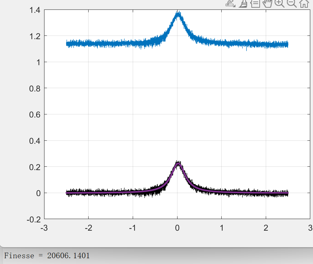
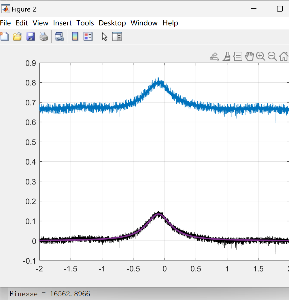
Today, Daniele and I cleaned mirrors one by one using pure water, alcohol, and the spin coater. Here are the measurements of finesse each time:
1. Initial value: 14,076
2. Clean Mirror 2: 20,606
3. Clean Mirror 4: 18,750
4. Clean Mirror 3: 18,762
5. Clean Mirror 1: 18,563
6. Reclean Mirror 4: 15,226 (unstable lock)
7. Reclean Mirror 4 again: 16,563 (unstable lock)
The finesse reached a maximum of 20,606 but finally was down. For the last two measurements, the locking state was unstable and noisy. Tomorrow we will optimize the locking status and re-measure.
| Xinyi Lu wrote: |
|
- Today we cleaned the environment and put the spin coater and microscope inside the airflow.
- Tomorrow, Daniele and I will clean the mirrors one by one using pure alcohol and water, and measure the finesse each time. If it does not improve, we will clean them with plasma.
|
|
| Attachment 1: 2nd_measurement_F20606.png
|
 |
| Attachment 2: 7th_measurement__F16563_bad_locking.png
|
 |
|
189
|
Wed Feb 14 17:20:26 2024 |
Xinyi Lu | Fixed | info | lasers and optics | Optical room | Cleaning of Mirrors |
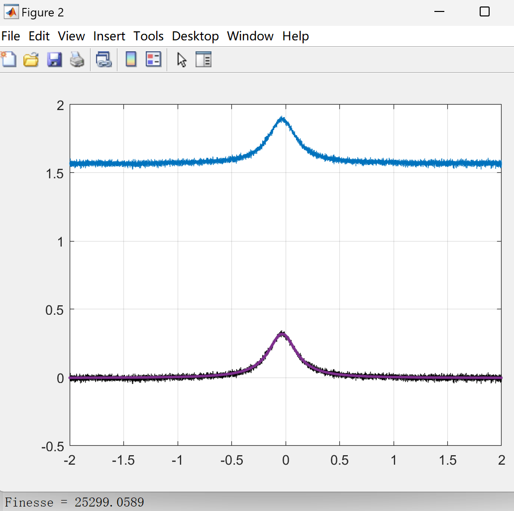
- Today, Daniele and I cleaned the cavity inside, recleaned the M2 and M4 and their mounts, optimized the locking, and the finesse is now about 25,000.
- Although it's lower than the expected 30,000-40,000, we decided to move on to the next step. In addition, the mount of M4 is near the end of the tuning range and may cause instability at high power.
- We adjusted the cavity length to match the repetition rate of the pulsed laser, and the FSR in air is 160.265 MHz.
- Tomorrow, we'll turn on the vacuum and use the pulsed laser to get resonance.
| Xinyi Lu wrote: |
|
Today, Daniele and I cleaned mirrors one by one using pure water, alcohol, and the spin coater. Here are the measurements of finesse each time:
1. Initial value: 14,076
2. Clean Mirror 2: 20,606
3. Clean Mirror 4: 18,750
4. Clean Mirror 3: 18,762
5. Clean Mirror 1: 18,563
6. Reclean Mirror 4: 15,226 (unstable lock)
7. Reclean Mirror 4 again: 16,563 (unstable lock)
The finesse reached a maximum of 20,606 but finally was down. For the last two measurements, the locking state was unstable and noisy. Tomorrow we will optimize the locking status and re-measure.
|
|
| Attachment 1: F_25299.png
|
 |
|
73
|
Mon Apr 4 13:58:23 2022 |
Manar Amer | Fixed | issue | detectors and electronics | utilities | Optical room | Clean Airflow Dust measurements |
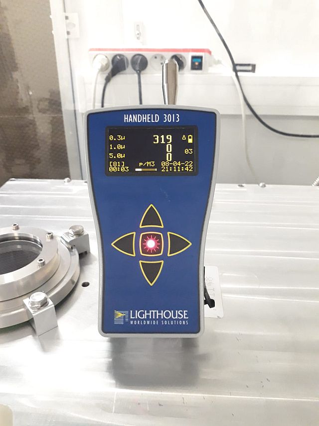
The dust meter cap was cleaned using Alcohol, and using the filter white cap the dust count was (0 Av. 10 min)
After the dust counter was hand held in direct airflow, it counted (1581 p/m3 Av. 2 min).
I tested the count also in the SAS, and it counted twice the amount ~ 4500 p/m3
Note: discussion on the next steps to take for the airflow filtering !!!!!!!! |
|
74
|
Fri Apr 8 19:27:12 2022 |
Manar Amer | Fixed | issue | detectors and electronics | utilities | Optical room | Clean Airflow Dust measurements |
Dust measurement done today on top of the SBox average 10min
| Manar Amer wrote: |
|
The dust meter cap was cleaned using Alcohol, and using the filter white cap the dust count was (0 Av. 10 min)
After the dust counter was hand held in direct airflow, it counted (1581 p/m3 Av. 2 min).
I tested the count also in the SAS, and it counted twice the amount ~ 4500 p/m3
Note: discussion on the next steps to take for the airflow filtering !!!!!!!!
|
|
| Attachment 1: 20220408_DustMeasurement.jpg
|
 |
|
18
|
Wed Oct 31 13:51:17 2018 |
Loïc Amoudry | Fixed | info | lasers and optics | Optical room | Change of the 3 ULE mirrors by 3 spare ULE mirrors |
First finesse measurement 20 266, FSR 133.351 MHz under vacuum |
| Attachment 1: Miroirs_à_1031_nm-ThomX_-_décembre2017.pdf
|
| Attachment 2: vacuum.isf
|
|
1
|
Wed Sep 26 18:12:44 2018 |
Loïc Amoudry | Fixed | info | lasers and optics | Optical room | Cavity polarization states (Koheras), Finesse of 2 polarization states |
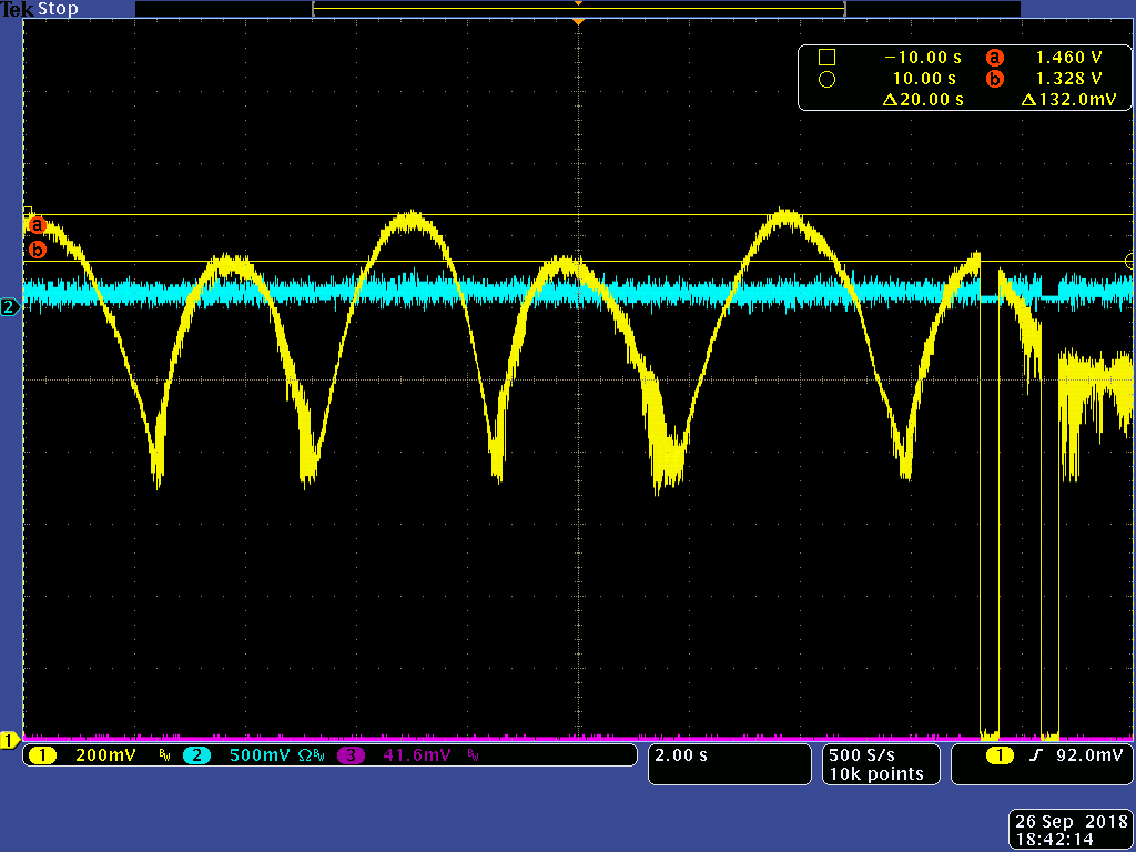
Measurments of Finesse with the 2 polarization states, let's call them H (higher) and L (lower): 24500 for the H and 23500 for the L.
We checked the polarization states in transmission of the FP cavity after a PBS. The H was stronger in PBS trans and the L stronger in PBS ref.
We measured the power in reflection of the PBS and added a half WP that we aligned with the PBS polarization. Then, to get the maximum power we had to tilt the half WP of 22° for the H and 18° for the L.
Finally we checked the extinction through half WP and PBS for H and L.
- For H : max 75 mW min 5 mW. Ratio 6.66%
- For L : max 70 mW min 4 mW. Ratio 5.7%
Right after Koheras : max 3.5 mW min 47 uW. Ratio 1.3%
|
| Attachment 1: Finesse_higher.isf
|
| Attachment 2: Finesse_lower.isf
|
| Attachment 3: The2polarizations_states_direct_trans.isf
|
| Attachment 4: The2polarizations_states_direct_trans.png
|
 |
|
45
|
Thu Dec 19 16:23:39 2019 |
Ronic Chiche | Fixed | info | lasers and optics | Optical room | Cavity beam axis moving with power |
how the cavity beam axis is moving during a lock when the cavity is hot ?
could it explain a part of the Transmission / Coupling signal decay ?
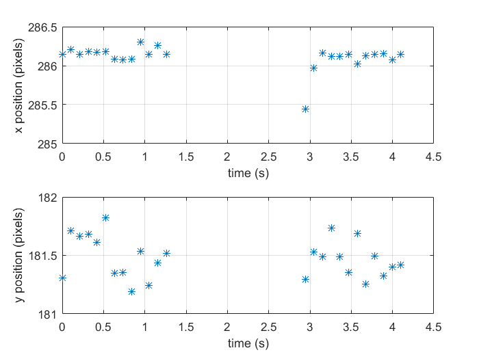
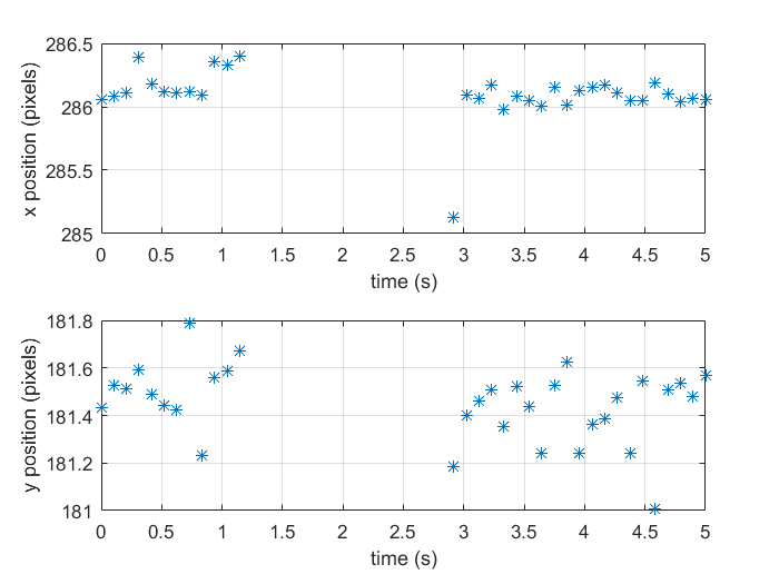
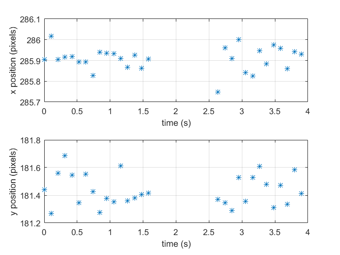
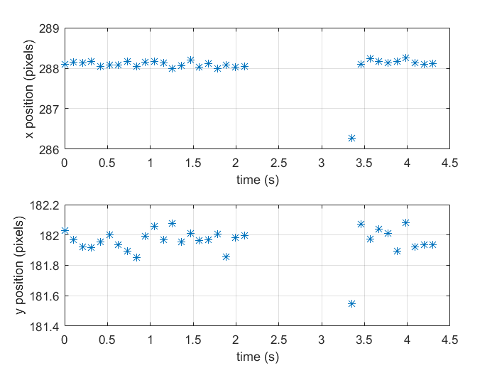
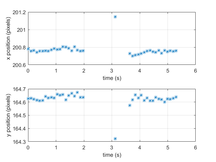
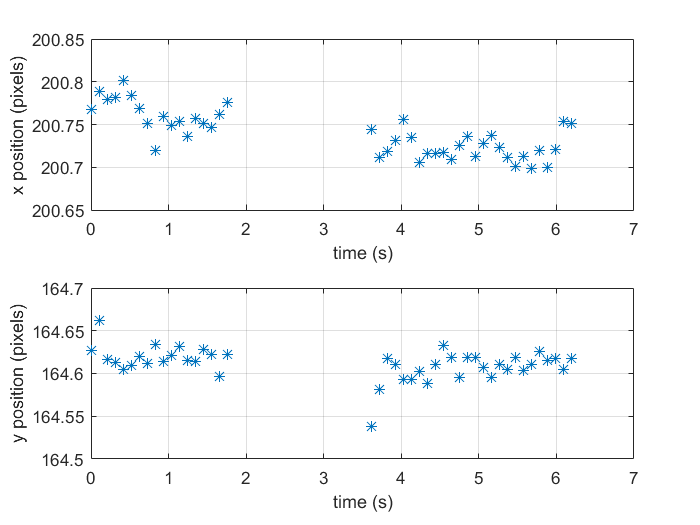
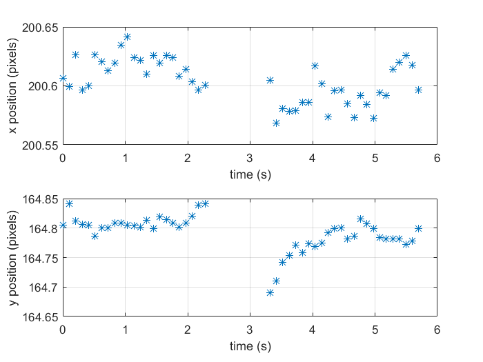
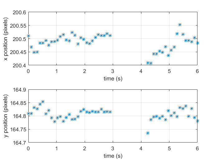
we placed 2 Basler camera, one at (30+Z) cm and the other at (85+Z) cm (Z is about 15cm) from the M3 mirror, we recorded the video during a lock and we analyzed the centroid X and Y displacement at 2A and 3A.
frames acquisition speed is a quite slow ~ 100ms => we need to acquire the frames faster !
with these data, the displacement is no more than some pixels, which means << 100µm ... it should be completely negligeable for photdiode thorlabs DET100 with ~10mm of diameter.
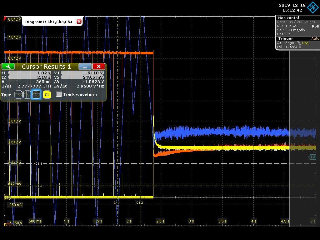
the last picture displays typical locking curves (before and after lock) :
- transmission : yellow
- coupling : orange
- PZT correction : blue |
| Attachment 1: Basler_30cm_2A_v1.png
|
 |
| Attachment 2: Basler_30cm_2A_v2.png
|
 |
| Attachment 3: Basler_30cm_3A_v1.png
|
 |
| Attachment 4: Basler_30cm_3A_v2.png
|
 |
| Attachment 5: Basler_85cm_2A_v1.png
|
 |
| Attachment 6: Basler_85cm_2A_v2.png
|
 |
| Attachment 7: Basler_85cm_3A_v1.png
|
 |
| Attachment 8: Basler_85cm_3A_v2.png
|
 |
| Attachment 9: Screenshot_2019-12-19_4_151242.png
|
 |
|
95
|
Wed Jun 8 11:10:17 2022 |
Manar Amer | Fixed | report | lasers and optics | detectors and electronics | software | Optical room | Cavity Lock |
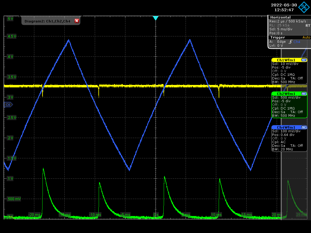
Start with the cavity lock images attached, taken from last week, at start we have a coupling ~ 5% and started improving on the alignment .
The image of 00 modes attached corresponds to the coupling seen on the oscilloscope.
We have a higher coupling with the 11 mode due to the size of the injected beam in comparison to mode
lenses were added to improve it. |
| Attachment 1: Screenshot_2022-05-30_0_125247.png
|
 |
| Attachment 2: 20220530_00_Mode.bmp
|
| Attachment 3: 11.bmp
|
|
97
|
Wed Jun 8 11:31:47 2022 |
Manar Amer | Fixed | report | lasers and optics | detectors and electronics | software | Optical room | Cavity Lock |
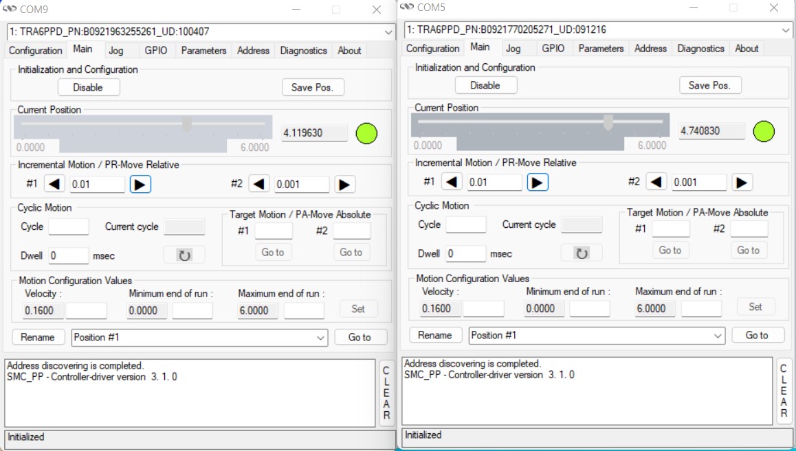
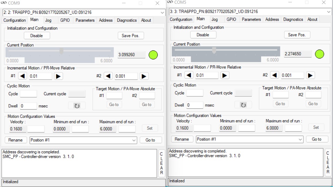
Current setup at SBox for locking the cavity
After spacial matching, the coupling increased to ~ 15 - 20 %
The locking was done for the fundamental mode, tried to improve the coupling with the motors, but the lock is very unstable to be investigated. (Note: the cavity in under normal pressure)
| Manar Amer wrote: |
|
Start with the cavity lock images attached, taken from last week, at start we have a coupling ~ 5% and started improving on the alignment .
The image of 00 modes attached corresponds to the coupling seen on the oscilloscope.
We have a higher coupling with the 11 mode due to the size of the injected beam in comparison to mode
lenses were added to improve it.
|
|
| Attachment 1: 20220607_SBox_Setup.png
|
 |
| Attachment 2: Ma1_Ma2_Horizontal_end-of-day.jpg
|
 |
| Attachment 3: Ma1_Ma2_Vertical_end-of-day.jpg
|
 |
|
98
|
Thu Jun 9 19:59:42 2022 |
Manar Amer | Fixed | report | lasers and optics | detectors and electronics | software | Optical room | Cavity Lock |
Cavity locked today under vacuum and no airflow, it is stable over a long time
the alignment was improved and an increase of the transmission by 20 % from its original value
unfortunately, data from the oscilloscope was saved, but it was not in the correct format (image) to show.
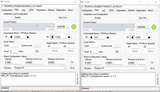
Attached ; the mode shape, the new motor positions.
| Manar Amer wrote: |
|
Current setup at SBox for locking the cavity
After spacial matching, the coupling increased to ~ 15 - 20 %
The locking was done for the fundamental mode, tried to improve the coupling with the motors, but the lock is very unstable to be investigated. (Note: the cavity in under normal pressure)
| Manar Amer wrote: |
|
Start with the cavity lock images attached, taken from last week, at start we have a coupling ~ 5% and started improving on the alignment .
The image of 00 modes attached corresponds to the coupling seen on the oscilloscope.
We have a higher coupling with the 11 mode due to the size of the injected beam in comparison to mode
lenses were added to improve it.
|
|
|
| Attachment 1: 00_Mode_Locked_Under_vacuum.bmp
|
| Attachment 2: Ma1_Ma2_Horizontal_end-of-day.jpg
|
 |
| Attachment 3: Ma1_Ma2_Vertical_end-of-day.jpg
|
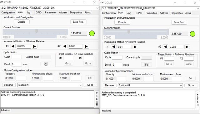 |
|
101
|
Wed Jul 6 18:34:12 2022 |
Manar Amer | Fixed | report | lasers and optics | detectors and electronics | software | Optical room | Cavity Lock |
Closing the series for the setup
The cavity was only locked @ 133.33 MHz but the Finesse was not measured
The FSR was changed to match the new laser MENHIR 216.6625 MHz
| Manar Amer wrote: |
|
Cavity locked today under vacuum and no airflow, it is stable over a long time
the alignment was improved and an increase of the transmission by 20 % from its original value
unfortunately, data from the oscilloscope was saved, but it was not in the correct format (image) to show.
Attached ; the mode shape, the new motor positions.
| Manar Amer wrote: |
|
Current setup at SBox for locking the cavity
After spacial matching, the coupling increased to ~ 15 - 20 %
The locking was done for the fundamental mode, tried to improve the coupling with the motors, but the lock is very unstable to be investigated. (Note: the cavity in under normal pressure)
| Manar Amer wrote: |
|
Start with the cavity lock images attached, taken from last week, at start we have a coupling ~ 5% and started improving on the alignment .
The image of 00 modes attached corresponds to the coupling seen on the oscilloscope.
We have a higher coupling with the 11 mode due to the size of the injected beam in comparison to mode
lenses were added to improve it.
|
|
|
|
|
119
|
Fri Jul 22 18:19:13 2022 |
Manar Amer | Fixed | report | lasers and optics | detectors and electronics | software | Optical room | CVBG stretching / Fiber Injection |
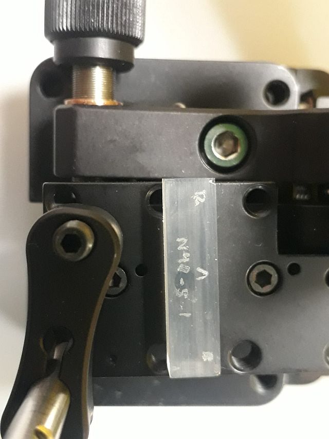
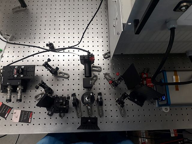
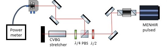
Before injecting into the amplifier, the pulse needs to be stretched using a CVBG, type attached.
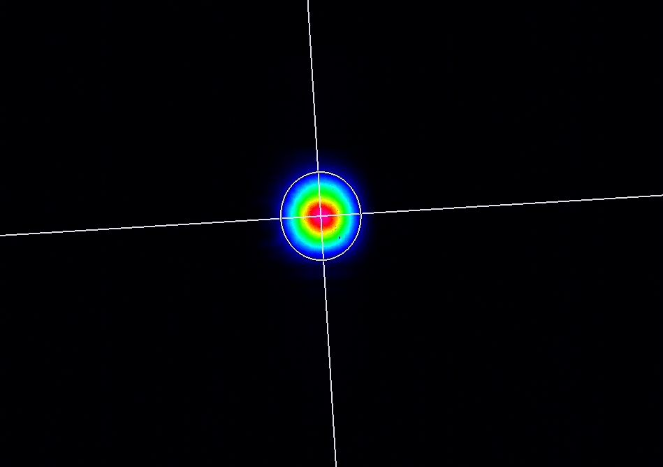
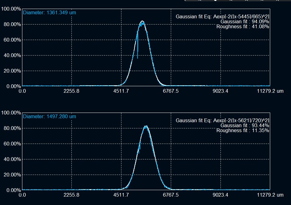
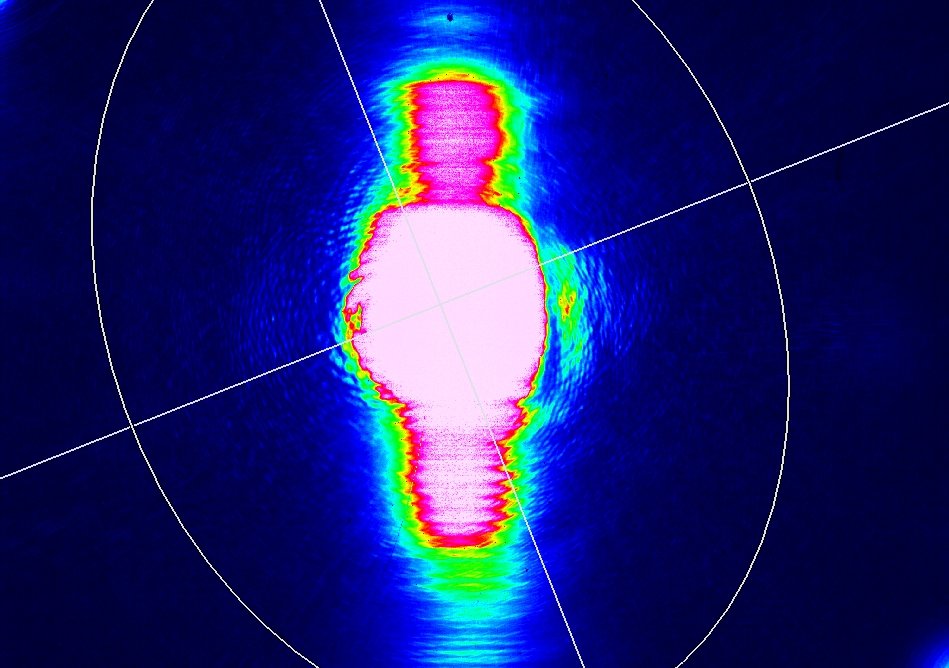
the CVBG is to be used at a small angle, the beam shape and spectrum after the PBS is attached.
After measuring the beam profile, a mirror was placed to direct all the power for fiber injection
power before the fiber is 13 mW and the power injected is 6.19 mW
|
| Attachment 1: CVBG.jpg
|
 |
| Attachment 2: beamafterCVBG.jpg
|
 |
| Attachment 3: beamafterCVBG_Fit.jpg
|
 |
| Attachment 4: beamafterCVBG_saturated.jpg
|
 |
| Attachment 5: SpectrumafterCVBGzoom.png
|
 |
| Attachment 6: CVBG_Injection_Setup.jpg
|
 |
| Attachment 7: 20220722_CVBG_stretching.jpeg
|
 |
|
131
|
Fri Aug 19 16:03:40 2022 |
Manar Amer | Fixed | report | lasers and optics | detectors and electronics | software | Optical room | CVBG stretching / Fiber Injection |
closing series
| Manar Amer wrote: |
|
Before injecting into the amplifier, the pulse needs to be stretched using a CVBG, type attached.
the CVBG is to be used at a small angle, the beam shape and spectrum after the PBS is attached.
After measuring the beam profile, a mirror was placed to direct all the power for fiber injection
power before the fiber is 13 mW and the power injected is 6.19 mW
|
|
|
51
|
Fri Jan 24 17:58:45 2020 |
Loïc Amoudry | Fixed | info | lasers and optics | Optical room | CFBG removed from ThomX CELIA amplifier |
The CFBG has been removed successfully and the amplifier is closed now.
The soldering machine had a calibration trouble and was sent to the company for review during holidays.
The output power has been checked and is the same as before (tested until 30W ouput power). |
|
116
|
Fri Jul 22 17:07:32 2022 |
Manar Amer | Fixed | report | lasers and optics | detectors and electronics | software | Optical room | CELIA amplifier installation + chiller |
Amplifier placed next to the pulsed laser on the table under the airflow
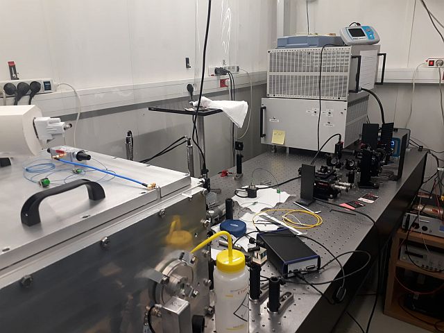
The output is in free space with height from the table of about 10 cm, note the injection height into the cavity is between 14 - 15 cm.
a power cable is placed but not plugged.
Connection to the computer is made using USB B on amplifier to USB A (note need a longer cable, the available on is too short)
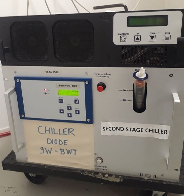
The cooling, to be connected to an outside chiller, will use the bottom one shown in the image attached.
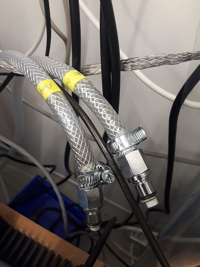
The two water tubes, from chiller to amplifier, has been marked. The size of the tubes from the amplifier fit inside the tubes from the chiller.
| Manar Amer wrote: |
|
The amplifier was installed on the optical table next to SBox table.
The CVBG that will be used for stretching before amplification needs cleaning (they are very fragile, 'ask victor for best method')
The software to drive the diodes of the amplifier we have is not the compatible one.
|
|
| Attachment 1: WhatsApp_Image_2022-07-22_at_4.26.24_PM.jpg
|
 |
| Attachment 2: WhatsApp_Image_2022-07-22_at_4.26.24_PM.jpg
|
 |
| Attachment 3: WhatsApp_Image_2022-07-22_at_5.02.24_PM.jpg
|
 |
|
120
|
Fri Jul 22 18:25:31 2022 |
Manar Amer | Fixed | report | lasers and optics | detectors and electronics | software | Optical room | CELIA amplifier installation + chiller |
The software to control the CELIA amplifier is on the laptop that was placed in ThomX bunker.
I have placed it in the PLIC room next to the SBox table.
it is called 'Alphanov Control Software'
| Manar Amer wrote: |
|
Amplifier placed next to the pulsed laser on the table under the airflow
The output is in free space with height from the table of about 10 cm, note the injection height into the cavity is between 14 - 15 cm.
a power cable is placed but not plugged.
Connection to the computer is made using USB B on amplifier to USB A (note need a longer cable, the available on is too short)
The cooling, to be connected to an outside chiller, will use the bottom one shown in the image attached.
The two water tubes, from chiller to amplifier, has been marked. The size of the tubes from the amplifier fit inside the tubes from the chiller.
| Manar Amer wrote: |
|
The amplifier was installed on the optical table next to SBox table.
The CVBG that will be used for stretching before amplification needs cleaning (they are very fragile, 'ask victor for best method')
The software to drive the diodes of the amplifier we have is not the compatible one.
|
|
|
|
129
|
Fri Aug 19 16:02:33 2022 |
Manar Amer | Fixed | report | lasers and optics | detectors and electronics | software | Optical room | CELIA amplifier installation + chiller |
Closing series
| Manar Amer wrote: |
|
The software to control the CELIA amplifier is on the laptop that was placed in ThomX bunker.
I have placed it in the PLIC room next to the SBox table.
it is called 'Alphanov Control Software'
| Manar Amer wrote: |
|
Amplifier placed next to the pulsed laser on the table under the airflow
The output is in free space with height from the table of about 10 cm, note the injection height into the cavity is between 14 - 15 cm.
a power cable is placed but not plugged.
Connection to the computer is made using USB B on amplifier to USB A (note need a longer cable, the available on is too short)
The cooling, to be connected to an outside chiller, will use the bottom one shown in the image attached.
The two water tubes, from chiller to amplifier, has been marked. The size of the tubes from the amplifier fit inside the tubes from the chiller.
| Manar Amer wrote: |
|
The amplifier was installed on the optical table next to SBox table.
The CVBG that will be used for stretching before amplification needs cleaning (they are very fragile, 'ask victor for best method')
The software to drive the diodes of the amplifier we have is not the compatible one.
|
|
|
|