ID |
Date |
Author |
Status |
Type |
Category |
Location |
Title |
|
261
|
Mon Aug 31 16:28:31 2026 |
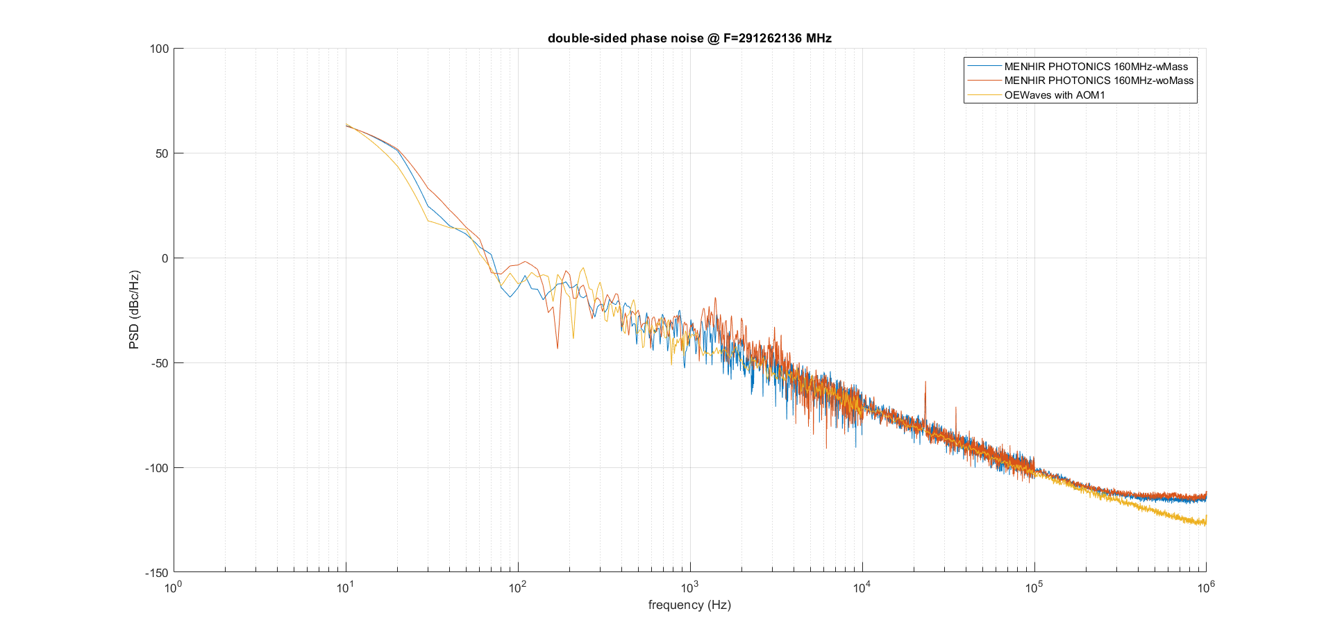
Ronic Chiche | Under Process | info | lasers and optics | Optical room | Menhir oscillator phase noise measurement | after the previous measurement, we installed similar dampers, than the ones used belows the aluminium breadboard, placed below the 4 Menhir 160MHz "feet", in contact with the aluminium breadboard.
- in red, phase noise measurement with the Sorbothane feet below the Menhir laser and below the aluminium breadboard.
- in blue,same measurment with an additionnal heavy mass placed in the middle of the breadboard.
| Ronic Chiche wrote: |
|
comparison of the Menhir 160MHz phase noise with the CW reference.
- in blue, the oscillators are placed on top of an aluminium breadboard, placed directly on an optical table (measurement made in june)
- in red, the oscillators are placed on top of an aluminium breadboard, placed directly on top of 4 feet with Thorlabs AV4/M Sorbothane dampers, above the NeoLase amplifier (measurement made last week)
=> similar behavior with phase noise increasing around 1kHz, compared to the reference.
| Ronic Chiche wrote: |
|
measurements made with Alice:
comparison between the CW OEwaves oscillator phase noise measured last week (2 measurements done with AOM, in red and orange) with the one made in 2022 (without AOM, in blue).
one observes a degradation of the performance of the oscillator by ~10dB in the region of interest 100Hz-100kHz
| Ronic Chiche wrote: |
|
with Alice, we installed the Menhir 160MHz oscillator on a breadboad placed on top of 4 damped feet around the amplifier.
we will do an heterodyne phase noise measurement vs the CW OEwaves oscillator.
the power at the output of the Menhir oscillator is about 150mW.
after injection in the fiber (N°3 blue jacket), we got about 75mW.
we installed the 2->1 coupler to make the beating.
BE CAREFUL, the coupler is polarization sensitive, so we add a half waveplate in the Menhir path to adust the polarization on the coupler, otherwise the output power can be very low.
the coupler attenuation is ~ 3.5dB on both inputs.
the OEwaves power is ~16mW at the input and we measured ~7mW at the output of the coupler for this channel.
the Menhir fiber coupled power is ~75mW and we measured ~26mW at the output of the coupler for this channel.
|
|
|
|
| Attachment 1: Mehnir_PN_plots.png
|  |
|
260
|
Mon Aug 31 16:15:46 2026 |
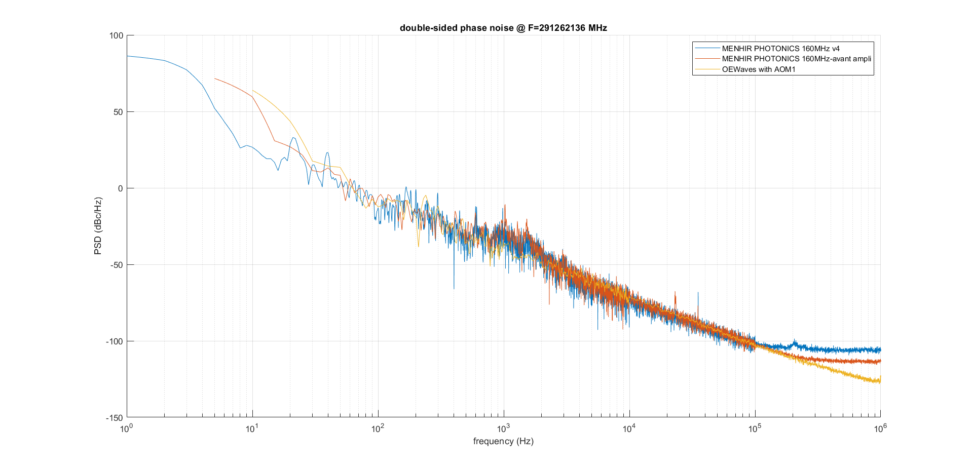
Ronic Chiche | Under Process | info | lasers and optics | Optical room | Menhir oscillator phase noise measurement | comparison of the Menhir 160MHz phase noise with the CW reference.
- in blue, the oscillators are placed on top of an aluminium breadboard, placed directly on an optical table (measurement made in june)
- in red, the oscillators are placed on top of an aluminium breadboard, placed directly on top of 4 feet with Thorlabs AV4/M Sorbothane dampers, above the NeoLase amplifier (measurement made last week)
=> similar behavior with phase noise increasing around 1kHz, compared to the reference.
| Ronic Chiche wrote: |
|
measurements made with Alice:
comparison between the CW OEwaves oscillator phase noise measured last week (2 measurements done with AOM, in red and orange) with the one made in 2022 (without AOM, in blue).
one observes a degradation of the performance of the oscillator by ~10dB in the region of interest 100Hz-100kHz
| Ronic Chiche wrote: |
|
with Alice, we installed the Menhir 160MHz oscillator on a breadboad placed on top of 4 damped feet around the amplifier.
we will do an heterodyne phase noise measurement vs the CW OEwaves oscillator.
the power at the output of the Menhir oscillator is about 150mW.
after injection in the fiber (N°3 blue jacket), we got about 75mW.
we installed the 2->1 coupler to make the beating.
BE CAREFUL, the coupler is polarization sensitive, so we add a half waveplate in the Menhir path to adust the polarization on the coupler, otherwise the output power can be very low.
the coupler attenuation is ~ 3.5dB on both inputs.
the OEwaves power is ~16mW at the input and we measured ~7mW at the output of the coupler for this channel.
the Menhir fiber coupled power is ~75mW and we measured ~26mW at the output of the coupler for this channel.
|
|
|
| Attachment 1: Mehnir_PN_plots.png
|  |
|
259
|
Mon Aug 31 15:14:04 2026 |
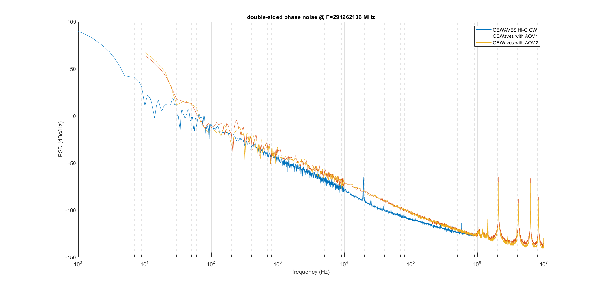
Ronic Chiche | Under Process | info | lasers and optics | Optical room | Menhir oscillator phase noise measurement | measurements made with Alice:
comparison between the CW OEwaves oscillator phase noise measured last week (2 measurements done with AOM, in red and orange) with the one made in 2022 (without AOM, in blue).
one observes a degradation of the performance of the oscillator by ~10dB in the region of interest 100Hz-100kHz
| Ronic Chiche wrote: |
|
with Alice, we installed the Menhir 160MHz oscillator on a breadboad placed on top of 4 damped feet around the amplifier.
we will do an heterodyne phase noise measurement vs the CW OEwaves oscillator.
the power at the output of the Menhir oscillator is about 150mW.
after injection in the fiber (N°3 blue jacket), we got about 75mW.
we installed the 2->1 coupler to make the beating.
BE CAREFUL, the coupler is polarization sensitive, so we add a half waveplate in the Menhir path to adust the polarization on the coupler, otherwise the output power can be very low.
the coupler attenuation is ~ 3.5dB on both inputs.
the OEwaves power is ~16mW at the input and we measured ~7mW at the output of the coupler for this channel.
the Menhir fiber coupled power is ~75mW and we measured ~26mW at the output of the coupler for this channel.
|
|
| Attachment 1: CW_OEwaves_phase_noise_comparison.png
|  |
|
258
|
Thu Aug 27 11:13:07 2026 |
Ronic Chiche | Under Process | info | lasers and optics | Optical room | Menhir oscillator phase noise measurement | with Alice, we installed the Menhir 160MHz oscillator on a breadboad placed on top of 4 damped feet around the amplifier.
we will do an heterodyne phase noise measurement vs the CW OEwaves oscillator.
the power at the output of the Menhir oscillator is about 150mW.
after injection in the fiber (N°3 blue jacket), we got about 75mW.
we installed the 2->1 coupler to make the beating.
BE CAREFUL, the coupler is polarization sensitive, so we add a half waveplate in the Menhir path to adust the polarization on the coupler, otherwise the output power can be very low.
the coupler attenuation is ~ 3.5dB on both inputs.
the OEwaves power is ~16mW at the input and we measured ~7mW at the output of the coupler for this channel.
the Menhir fiber coupled power is ~75mW and we measured ~26mW at the output of the coupler for this channel.
|
|
257
|
Thu Aug 27 11:08:44 2026 |
Ronic Chiche | Fixed | info | lasers and optics | Optical room | fiber patch cables attenuation measurements | attenuation with 1 mating sleeve :
green jacket fiber : -0.4 dB
blue jacket fiber N°1 : -0.5 dB
blue jacket fiber N°2 : -0.27 dB
blue jacket fiber N°3 : -0.13 dB
blue jacket fiber N°4 : -1.4 dB
we should try to polish at least the fiber 4 which seems faulty.
|
|
256
|
Wed Aug 26 16:12:13 2026 |
Ronic Chiche | Under Process | info | mechanics | lasers and optics | cabling | Optical room | Neolase amplifier installation | this morning, I tried to restart the controller but all the temperatures values on the NeoCon software were stuck to 0°C !
and nothing changes after a reset of controller (press 3 secs on start/stop button), a switch on/off or a power cord removed.
=> an email has been sent to NeoLas/AMS.
| Ronic Chiche wrote: |
|
I installed 4 steel feets around the amplifier, with rubber damping absorbers on top, to put later the oscillator optical breadboard on top of it.
as the amplifier controller is directly connected to a computer (and not on a network) with no native DHCP server, I had to install a local DHCP server on the computer.
computer IP address: 192.168.1.1
the present (DHCP) IP address of the amplifier controller is: IP 192.168.1.2 / MAC 00-01-05-92-BE-DA
it seems the NeoCon software is not able to connect with the hostname NEOYB2502, so I used the IP address, instead : 192.168.1.2 and it worked.
now, I get access to the different software windows.
as it is a cold start, I had to press the "stop/reset" button for 3 seconds.
after that, everything seems ok (no errors nor warnings), except for the preamplifier window which is in fault as there is no laser seed at the input.
(input power should be in the range -10dBm / +10dBm <=> 0.1mW / 10mW)
so, the next step would be to move the oscillator breadboard on top of the amplifier and connect the oscillator to the amplifier to check the amplifier start.
| Ronic Chiche wrote: |
|
I connected the power supplies, laser controller and laser head together with all the cables... with no scheme in the manual.
hopefully, the cables are labeled at both ends. all the main cable connectors have been secured with 2 screws.
I add a little scheme to help.
for the cables between controller and power supplies, attached to the main cables, there are twin wires, black and red, with a little green connector at the end...
and I don't know where to plug it... my feeling is these little green connectors may stay unconnected (they have been intended for a different or older configuration).
| Ronic Chiche wrote: |
|
an email from Neolase/AMS claims that 1.7Lpm is a normal flow (previous tests at 1.2Lpm have been done successfully with a reduced output power of the amplifier).
so, I connected the amplifier, refilled the chiller and started a test for the day : 0.9bar / 1.7Lpm / 22°C (no leakage at all).
but the amplifier is not running... it's to check if there is no basic issue.
| Ronic Chiche wrote: |
|
as soon as I connect the amplifier to the pipes, the flow decreases to 1.7Lpm.
and the filling process is very long and noisy, as there was something blocking the filling process...
| Ronic Chiche wrote: |
|
I cut a small part of the black pipe on the amplifier side (could it be slightly deformed by a try with an other type of adapter ?), with the dedicated tool, changed the adapter and plugged it more firmly in the pipe (pipe deeply inserted in the adapter).
it seems, there is no more leakage.
measured pressure and flow are 0.9 bar and 4.7Lpm => OK without amplifier.
| Ronic Chiche wrote: |
|
now, I installed the long pipes (2x 3m) in closed loop (without the amplifier connected), but the exact ones used to connect the laser, with the same pipe adapters.
after the compression process, the chiller works at 0.9 bar and the measured flow is 4.7Lpm.
so, it's still OK !
after a long time, I observed a small leakage on the "male" adapter on the amplifier side.
| Ronic Chiche wrote: |
|
I drained the chiller to install again the short pipe (< 1m) in closed loop.
then, I filled again the chiller and did the compression process to obtain 1bar.
in that case, the flow measured by the chiller is correct about 5.8Lpm.
PS : the correct length for the previous calculation is 6m (2x 3m) and not 3m...
in that case, the flow should be ~ 15Lpm (and not 22 Lpm)
| )Ronic Chiche wrote: |
|
pipes are maybe too long ?
we can use the Darcy-Weisbach + Blasius laws (non linear laws).
I asked to ChatGPT, Claude, Mistral and MathGPT to solve it with these parameters :
L ~ 3m
D = 1 cm
water at 20°C
dP = 0.7 bar
they all found ~ 22-23L/min
so, the tube length should not be the problem... to be investiguated.
| Ronic Chiche wrote: |
|
now, I connected the chiller circuit to the amplifier, thanks to the adapters.
chiller IN => blue pipe => laser OUT
chiller OUT => black pipe => laser IN
after several filling and compression procedure, the flow is only 1.7Lpm and the pressure is 0.8 bar.
the temperature has been set to 20°C according to the manual operating range 18-23°C.
the flow is too low !
according to the manual, the flow should be 3-5Lpm !
a very small leakage appears if the mechanical constrains on the pipe is too high.
so, I separated the IN and OUT pipes to release this constrain and fixed the pipes to keep the position.
| Ronic Chiche wrote: |
|
we have all the adaptor plugs for connecting the chiller.
so, I tested first the chiller connected in closed loop (on itself).
there is no manual, so procedure is not completely clear...
DO NOT PLUG ANYTHING BEFORE THE CHILLER ASK FOR IT
ONE MUST FOLLOW THE PROCEDURE ON THE CHILLER DISPLAY
1) if the chiller circuit is full of coolant liquid,
one must start by a System Startup -> Draining
(a trash tank and the hose will be need for emptying the circuit)
2) once the chiller circuit is empty
one must continue by System Startup -> Filling
(a clean demineralized water tank and the hose will be need for filling the circuit)
=> OK !
the chiller is able the fill and drain its circuit.
I saw the cooling water circulating in the closed loop.
|
|
|
|
|
|
|
|
|
|
|
|
255
|
Tue Aug 25 16:27:29 2026 |
Ronic Chiche | Under Process | info | mechanics | lasers and optics | cabling | Optical room | Neolase amplifier installation | I installed 4 steel feets around the amplifier, with rubber damping absorbers on top, to put later the oscillator optical breadboard on top of it.
as the amplifier controller is directly connected to a computer (and not on a network) with no native DHCP server, I had to install a local DHCP server on the computer.
computer IP address: 192.168.1.1
the present (DHCP) IP address of the amplifier controller is: IP 192.168.1.2 / MAC 00-01-05-92-BE-DA
it seems the NeoCon software is not able to connect with the hostname NEOYB2502, so I used the IP address, instead : 192.168.1.2 and it worked.
now, I get access to the different software windows.
as it is a cold start, I had to press the "stop/reset" button for 3 seconds.
after that, everything seems ok (no errors nor warnings), except for the preamplifier window which is in fault as there is no laser seed at the input.
(input power should be in the range -10dBm / +10dBm <=> 0.1mW / 10mW)
so, the next step would be to move the oscillator breadboard on top of the amplifier and connect the oscillator to the amplifier to check the amplifier start.
| Ronic Chiche wrote: |
|
I connected the power supplies, laser controller and laser head together with all the cables... with no scheme in the manual.
hopefully, the cables are labeled at both ends. all the main cable connectors have been secured with 2 screws.
I add a little scheme to help.
for the cables between controller and power supplies, attached to the main cables, there are twin wires, black and red, with a little green connector at the end...
and I don't know where to plug it... my feeling is these little green connectors may stay unconnected (they have been intended for a different or older configuration).
| Ronic Chiche wrote: |
|
an email from Neolase/AMS claims that 1.7Lpm is a normal flow (previous tests at 1.2Lpm have been done successfully with a reduced output power of the amplifier).
so, I connected the amplifier, refilled the chiller and started a test for the day : 0.9bar / 1.7Lpm / 22°C (no leakage at all).
but the amplifier is not running... it's to check if there is no basic issue.
| Ronic Chiche wrote: |
|
as soon as I connect the amplifier to the pipes, the flow decreases to 1.7Lpm.
and the filling process is very long and noisy, as there was something blocking the filling process...
| Ronic Chiche wrote: |
|
I cut a small part of the black pipe on the amplifier side (could it be slightly deformed by a try with an other type of adapter ?), with the dedicated tool, changed the adapter and plugged it more firmly in the pipe (pipe deeply inserted in the adapter).
it seems, there is no more leakage.
measured pressure and flow are 0.9 bar and 4.7Lpm => OK without amplifier.
| Ronic Chiche wrote: |
|
now, I installed the long pipes (2x 3m) in closed loop (without the amplifier connected), but the exact ones used to connect the laser, with the same pipe adapters.
after the compression process, the chiller works at 0.9 bar and the measured flow is 4.7Lpm.
so, it's still OK !
after a long time, I observed a small leakage on the "male" adapter on the amplifier side.
| Ronic Chiche wrote: |
|
I drained the chiller to install again the short pipe (< 1m) in closed loop.
then, I filled again the chiller and did the compression process to obtain 1bar.
in that case, the flow measured by the chiller is correct about 5.8Lpm.
PS : the correct length for the previous calculation is 6m (2x 3m) and not 3m...
in that case, the flow should be ~ 15Lpm (and not 22 Lpm)
| )Ronic Chiche wrote: |
|
pipes are maybe too long ?
we can use the Darcy-Weisbach + Blasius laws (non linear laws).
I asked to ChatGPT, Claude, Mistral and MathGPT to solve it with these parameters :
L ~ 3m
D = 1 cm
water at 20°C
dP = 0.7 bar
they all found ~ 22-23L/min
so, the tube length should not be the problem... to be investiguated.
| Ronic Chiche wrote: |
|
now, I connected the chiller circuit to the amplifier, thanks to the adapters.
chiller IN => blue pipe => laser OUT
chiller OUT => black pipe => laser IN
after several filling and compression procedure, the flow is only 1.7Lpm and the pressure is 0.8 bar.
the temperature has been set to 20°C according to the manual operating range 18-23°C.
the flow is too low !
according to the manual, the flow should be 3-5Lpm !
a very small leakage appears if the mechanical constrains on the pipe is too high.
so, I separated the IN and OUT pipes to release this constrain and fixed the pipes to keep the position.
| Ronic Chiche wrote: |
|
we have all the adaptor plugs for connecting the chiller.
so, I tested first the chiller connected in closed loop (on itself).
there is no manual, so procedure is not completely clear...
DO NOT PLUG ANYTHING BEFORE THE CHILLER ASK FOR IT
ONE MUST FOLLOW THE PROCEDURE ON THE CHILLER DISPLAY
1) if the chiller circuit is full of coolant liquid,
one must start by a System Startup -> Draining
(a trash tank and the hose will be need for emptying the circuit)
2) once the chiller circuit is empty
one must continue by System Startup -> Filling
(a clean demineralized water tank and the hose will be need for filling the circuit)
=> OK !
the chiller is able the fill and drain its circuit.
I saw the cooling water circulating in the closed loop.
|
|
|
|
|
|
|
|
|
|
|
254
|
Tue Aug 25 12:09:30 2026 |
Ronic Chiche | Under Process | info | mechanics | lasers and optics | cabling | Optical room | Neolase amplifier installation | I connected the power supplies, laser controller and laser head together with all the cables... with no scheme in the manual.
hopefully, the cables are labeled at both ends. all the main cable connectors have been secured with 2 screws.
I add a little scheme to help.
for the cables between controller and power supplies, attached to the main cables, there are twin wires, black and red, with a little green connector at the end...
and I don't know where to plug it... my feeling is these little green connectors may stay unconnected (they have been intended for a different or older configuration).
| Ronic Chiche wrote: |
|
an email from Neolase/AMS claims that 1.7Lpm is a normal flow (previous tests at 1.2Lpm have been done successfully with a reduced output power of the amplifier).
so, I connected the amplifier, refilled the chiller and started a test for the day : 0.9bar / 1.7Lpm / 22°C (no leakage at all).
but the amplifier is not running... it's to check if there is no basic issue.
| Ronic Chiche wrote: |
|
as soon as I connect the amplifier to the pipes, the flow decreases to 1.7Lpm.
and the filling process is very long and noisy, as there was something blocking the filling process...
| Ronic Chiche wrote: |
|
I cut a small part of the black pipe on the amplifier side (could it be slightly deformed by a try with an other type of adapter ?), with the dedicated tool, changed the adapter and plugged it more firmly in the pipe (pipe deeply inserted in the adapter).
it seems, there is no more leakage.
measured pressure and flow are 0.9 bar and 4.7Lpm => OK without amplifier.
| Ronic Chiche wrote: |
|
now, I installed the long pipes (2x 3m) in closed loop (without the amplifier connected), but the exact ones used to connect the laser, with the same pipe adapters.
after the compression process, the chiller works at 0.9 bar and the measured flow is 4.7Lpm.
so, it's still OK !
after a long time, I observed a small leakage on the "male" adapter on the amplifier side.
| Ronic Chiche wrote: |
|
I drained the chiller to install again the short pipe (< 1m) in closed loop.
then, I filled again the chiller and did the compression process to obtain 1bar.
in that case, the flow measured by the chiller is correct about 5.8Lpm.
PS : the correct length for the previous calculation is 6m (2x 3m) and not 3m...
in that case, the flow should be ~ 15Lpm (and not 22 Lpm)
| )Ronic Chiche wrote: |
|
pipes are maybe too long ?
we can use the Darcy-Weisbach + Blasius laws (non linear laws).
I asked to ChatGPT, Claude, Mistral and MathGPT to solve it with these parameters :
L ~ 3m
D = 1 cm
water at 20°C
dP = 0.7 bar
they all found ~ 22-23L/min
so, the tube length should not be the problem... to be investiguated.
| Ronic Chiche wrote: |
|
now, I connected the chiller circuit to the amplifier, thanks to the adapters.
chiller IN => blue pipe => laser OUT
chiller OUT => black pipe => laser IN
after several filling and compression procedure, the flow is only 1.7Lpm and the pressure is 0.8 bar.
the temperature has been set to 20°C according to the manual operating range 18-23°C.
the flow is too low !
according to the manual, the flow should be 3-5Lpm !
a very small leakage appears if the mechanical constrains on the pipe is too high.
so, I separated the IN and OUT pipes to release this constrain and fixed the pipes to keep the position.
| Ronic Chiche wrote: |
|
we have all the adaptor plugs for connecting the chiller.
so, I tested first the chiller connected in closed loop (on itself).
there is no manual, so procedure is not completely clear...
DO NOT PLUG ANYTHING BEFORE THE CHILLER ASK FOR IT
ONE MUST FOLLOW THE PROCEDURE ON THE CHILLER DISPLAY
1) if the chiller circuit is full of coolant liquid,
one must start by a System Startup -> Draining
(a trash tank and the hose will be need for emptying the circuit)
2) once the chiller circuit is empty
one must continue by System Startup -> Filling
(a clean demineralized water tank and the hose will be need for filling the circuit)
=> OK !
the chiller is able the fill and drain its circuit.
I saw the cooling water circulating in the closed loop.
|
|
|
|
|
|
|
|
|
| Attachment 1: Neolaser_amplifier_connection.pdf
|
|
253
|
Tue Aug 25 09:47:01 2026 |
Ronic Chiche | Under Process | info | mechanics | lasers and optics | cabling | Optical room | Neolase amplifier installation | an email from Neolase/AMS claims that 1.7Lpm is a normal flow (previous tests at 1.2Lpm have been done successfully with a reduced output power of the amplifier).
so, I connected the amplifier, refilled the chiller and started a test for the day : 0.9bar / 1.7Lpm / 22°C (no leakage at all).
but the amplifier is not running... it's to check if there is no basic issue.
status at the end of the day : 0.8bar / 1.7Lpm / 22°C (no leakage at all).
| Ronic Chiche wrote: |
|
as soon as I connect the amplifier to the pipes, the flow decreases to 1.7Lpm.
and the filling process is very long and noisy, as there was something blocking the filling process...
| Ronic Chiche wrote: |
|
I cut a small part of the black pipe on the amplifier side (could it be slightly deformed by a try with an other type of adapter ?), with the dedicated tool, changed the adapter and plugged it more firmly in the pipe (pipe deeply inserted in the adapter).
it seems, there is no more leakage.
measured pressure and flow are 0.9 bar and 4.7Lpm => OK without amplifier.
| Ronic Chiche wrote: |
|
now, I installed the long pipes (2x 3m) in closed loop (without the amplifier connected), but the exact ones used to connect the laser, with the same pipe adapters.
after the compression process, the chiller works at 0.9 bar and the measured flow is 4.7Lpm.
so, it's still OK !
after a long time, I observed a small leakage on the "male" adapter on the amplifier side.
| Ronic Chiche wrote: |
|
I drained the chiller to install again the short pipe (< 1m) in closed loop.
then, I filled again the chiller and did the compression process to obtain 1bar.
in that case, the flow measured by the chiller is correct about 5.8Lpm.
PS : the correct length for the previous calculation is 6m (2x 3m) and not 3m...
in that case, the flow should be ~ 15Lpm (and not 22 Lpm)
| )Ronic Chiche wrote: |
|
pipes are maybe too long ?
we can use the Darcy-Weisbach + Blasius laws (non linear laws).
I asked to ChatGPT, Claude, Mistral and MathGPT to solve it with these parameters :
L ~ 3m
D = 1 cm
water at 20°C
dP = 0.7 bar
they all found ~ 22-23L/min
so, the tube length should not be the problem... to be investiguated.
| Ronic Chiche wrote: |
|
now, I connected the chiller circuit to the amplifier, thanks to the adapters.
chiller IN => blue pipe => laser OUT
chiller OUT => black pipe => laser IN
after several filling and compression procedure, the flow is only 1.7Lpm and the pressure is 0.8 bar.
the temperature has been set to 20°C according to the manual operating range 18-23°C.
the flow is too low !
according to the manual, the flow should be 3-5Lpm !
a very small leakage appears if the mechanical constrains on the pipe is too high.
so, I separated the IN and OUT pipes to release this constrain and fixed the pipes to keep the position.
| Ronic Chiche wrote: |
|
we have all the adaptor plugs for connecting the chiller.
so, I tested first the chiller connected in closed loop (on itself).
there is no manual, so procedure is not completely clear...
DO NOT PLUG ANYTHING BEFORE THE CHILLER ASK FOR IT
ONE MUST FOLLOW THE PROCEDURE ON THE CHILLER DISPLAY
1) if the chiller circuit is full of coolant liquid,
one must start by a System Startup -> Draining
(a trash tank and the hose will be need for emptying the circuit)
2) once the chiller circuit is empty
one must continue by System Startup -> Filling
(a clean demineralized water tank and the hose will be need for filling the circuit)
=> OK !
the chiller is able the fill and drain its circuit.
I saw the cooling water circulating in the closed loop.
|
|
|
|
|
|
|
|
|
252
|
Fri Aug 7 11:41:17 2026 |
Ronic Chiche | Under Process | info | mechanics | lasers and optics | cabling | Optical room | Neolase amplifier installation | as soon as I connect the amplifier to the pipes, the flow decreases to 1.7Lpm.
and the filling process is very long and noisy, as there was something blocking the filling process...
| Ronic Chiche wrote: |
|
I cut a small part of the black pipe on the amplifier side (could it be slightly deformed by a try with an other type of adapter ?), with the dedicated tool, changed the adapter and plugged it more firmly in the pipe (pipe deeply inserted in the adapter).
it seems, there is no more leakage.
measured pressure and flow are 0.9 bar and 4.7Lpm => OK without amplifier.
| Ronic Chiche wrote: |
|
now, I installed the long pipes (2x 3m) in closed loop (without the amplifier connected), but the exact ones used to connect the laser, with the same pipe adapters.
after the compression process, the chiller works at 0.9 bar and the measured flow is 4.7Lpm.
so, it's still OK !
after a long time, I observed a small leakage on the "male" adapter on the amplifier side.
| Ronic Chiche wrote: |
|
I drained the chiller to install again the short pipe (< 1m) in closed loop.
then, I filled again the chiller and did the compression process to obtain 1bar.
in that case, the flow measured by the chiller is correct about 5.8Lpm.
PS : the correct length for the previous calculation is 6m (2x 3m) and not 3m...
in that case, the flow should be ~ 15Lpm (and not 22 Lpm)
| )Ronic Chiche wrote: |
|
pipes are maybe too long ?
we can use the Darcy-Weisbach + Blasius laws (non linear laws).
I asked to ChatGPT, Claude, Mistral and MathGPT to solve it with these parameters :
L ~ 3m
D = 1 cm
water at 20°C
dP = 0.7 bar
they all found ~ 22-23L/min
so, the tube length should not be the problem... to be investiguated.
| Ronic Chiche wrote: |
|
now, I connected the chiller circuit to the amplifier, thanks to the adapters.
chiller IN => blue pipe => laser OUT
chiller OUT => black pipe => laser IN
after several filling and compression procedure, the flow is only 1.7Lpm and the pressure is 0.8 bar.
the temperature has been set to 20°C according to the manual operating range 18-23°C.
the flow is too low !
according to the manual, the flow should be 3-5Lpm !
a very small leakage appears if the mechanical constrains on the pipe is too high.
so, I separated the IN and OUT pipes to release this constrain and fixed the pipes to keep the position.
| Ronic Chiche wrote: |
|
we have all the adaptor plugs for connecting the chiller.
so, I tested first the chiller connected in closed loop (on itself).
there is no manual, so procedure is not completely clear...
DO NOT PLUG ANYTHING BEFORE THE CHILLER ASK FOR IT
ONE MUST FOLLOW THE PROCEDURE ON THE CHILLER DISPLAY
1) if the chiller circuit is full of coolant liquid,
one must start by a System Startup -> Draining
(a trash tank and the hose will be need for emptying the circuit)
2) once the chiller circuit is empty
one must continue by System Startup -> Filling
(a clean demineralized water tank and the hose will be need for filling the circuit)
=> OK !
the chiller is able the fill and drain its circuit.
I saw the cooling water circulating in the closed loop.
|
|
|
|
|
|
|
|
251
|
Fri Aug 7 10:59:52 2026 |
Ronic Chiche | Under Process | info | mechanics | lasers and optics | cabling | Optical room | Neolase amplifier installation | I cut a small part of the black pipe on the amplifier side (could it be slightly deformed by a try with an other type of adapter ?), with the dedicated tool, changed the adapter and plugged it more firmly in the pipe (pipe deeply inserted in the adapter).
it seems, there is no more leakage.
measured pressure and flow are 0.9 bar and 4.7Lpm => OK without amplifier.
| Ronic Chiche wrote: |
|
now, I installed the long pipes (2x 3m) in closed loop (without the amplifier connected), but the exact ones used to connect the laser, with the same pipe adapters.
after the compression process, the chiller works at 0.9 bar and the measured flow is 4.7Lpm.
so, it's still OK !
after a long time, I observed a small leakage on the "male" adapter on the amplifier side.
| Ronic Chiche wrote: |
|
I drained the chiller to install again the short pipe (< 1m) in closed loop.
then, I filled again the chiller and did the compression process to obtain 1bar.
in that case, the flow measured by the chiller is correct about 5.8Lpm.
PS : the correct length for the previous calculation is 6m (2x 3m) and not 3m...
in that case, the flow should be ~ 15Lpm (and not 22 Lpm)
| )Ronic Chiche wrote: |
|
pipes are maybe too long ?
we can use the Darcy-Weisbach + Blasius laws (non linear laws).
I asked to ChatGPT, Claude, Mistral and MathGPT to solve it with these parameters :
L ~ 3m
D = 1 cm
water at 20°C
dP = 0.7 bar
they all found ~ 22-23L/min
so, the tube length should not be the problem... to be investiguated.
| Ronic Chiche wrote: |
|
now, I connected the chiller circuit to the amplifier, thanks to the adapters.
chiller IN => blue pipe => laser OUT
chiller OUT => black pipe => laser IN
after several filling and compression procedure, the flow is only 1.7Lpm and the pressure is 0.8 bar.
the temperature has been set to 20°C according to the manual operating range 18-23°C.
the flow is too low !
according to the manual, the flow should be 3-5Lpm !
a very small leakage appears if the mechanical constrains on the pipe is too high.
so, I separated the IN and OUT pipes to release this constrain and fixed the pipes to keep the position.
| Ronic Chiche wrote: |
|
we have all the adaptor plugs for connecting the chiller.
so, I tested first the chiller connected in closed loop (on itself).
there is no manual, so procedure is not completely clear...
DO NOT PLUG ANYTHING BEFORE THE CHILLER ASK FOR IT
ONE MUST FOLLOW THE PROCEDURE ON THE CHILLER DISPLAY
1) if the chiller circuit is full of coolant liquid,
one must start by a System Startup -> Draining
(a trash tank and the hose will be need for emptying the circuit)
2) once the chiller circuit is empty
one must continue by System Startup -> Filling
(a clean demineralized water tank and the hose will be need for filling the circuit)
=> OK !
the chiller is able the fill and drain its circuit.
I saw the cooling water circulating in the closed loop.
|
|
|
|
|
|
|
250
|
Thu Aug 6 15:12:49 2026 |
Ronic Chiche | Under Process | info | mechanics | lasers and optics | cabling | Optical room | Neolase amplifier installation | now, I installed the long pipes (2x 3m) in closed loop (without the amplifier connected), but the exact ones used to connect the laser, with the same pipe adapters.
after the compression process, the chiller works at 0.9 bar and the measured flow is 4.7Lpm.
so, it's still OK !
after a long time, I observed a small leakage on the "male" adapter on the amplifier side.
| Ronic Chiche wrote: |
|
I drained the chiller to install again the short pipe (< 1m) in closed loop.
then, I filled again the chiller and did the compression process to obtain 1bar.
in that case, the flow measured by the chiller is correct about 5.8Lpm.
PS : the correct length for the previous calculation is 6m (2x 3m) and not 3m...
in that case, the flow should be ~ 15Lpm (and not 22 Lpm)
| )Ronic Chiche wrote: |
|
pipes are maybe too long ?
we can use the Darcy-Weisbach + Blasius laws (non linear laws).
I asked to ChatGPT, Claude, Mistral and MathGPT to solve it with these parameters :
L ~ 3m
D = 1 cm
water at 20°C
dP = 0.7 bar
they all found ~ 22-23L/min
so, the tube length should not be the problem... to be investiguated.
| Ronic Chiche wrote: |
|
now, I connected the chiller circuit to the amplifier, thanks to the adapters.
chiller IN => blue pipe => laser OUT
chiller OUT => black pipe => laser IN
after several filling and compression procedure, the flow is only 1.7Lpm and the pressure is 0.8 bar.
the temperature has been set to 20°C according to the manual operating range 18-23°C.
the flow is too low !
according to the manual, the flow should be 3-5Lpm !
a very small leakage appears if the mechanical constrains on the pipe is too high.
so, I separated the IN and OUT pipes to release this constrain and fixed the pipes to keep the position.
| Ronic Chiche wrote: |
|
we have all the adaptor plugs for connecting the chiller.
so, I tested first the chiller connected in closed loop (on itself).
there is no manual, so procedure is not completely clear...
DO NOT PLUG ANYTHING BEFORE THE CHILLER ASK FOR IT
ONE MUST FOLLOW THE PROCEDURE ON THE CHILLER DISPLAY
1) if the chiller circuit is full of coolant liquid,
one must start by a System Startup -> Draining
(a trash tank and the hose will be need for emptying the circuit)
2) once the chiller circuit is empty
one must continue by System Startup -> Filling
(a clean demineralized water tank and the hose will be need for filling the circuit)
=> OK !
the chiller is able the fill and drain its circuit.
I saw the cooling water circulating in the closed loop.
|
|
|
|
|
|
249
|
Thu Aug 6 14:49:32 2026 |
Ronic Chiche | Under Process | info | mechanics | lasers and optics | cabling | Optical room | Neolase amplifier installation | I drained the chiller to install again the short pipe (< 1m) in closed loop.
then, I filled again the chiller and did the compression process to obtain 1bar.
in that case, the flow measured by the chiller is correct about 5.8Lpm.
PS : the correct length for the previous calculation is 6m (2x 3m) and not 3m...
in that case, the flow should be ~ 15Lpm (and not 22 Lpm)
| )Ronic Chiche wrote: |
|
pipes are maybe too long ?
we can use the Darcy-Weisbach + Blasius laws (non linear laws).
I asked to ChatGPT, Claude, Mistral and MathGPT to solve it with these parameters :
L ~ 3m
D = 1 cm
water at 20°C
dP = 0.7 bar
they all found ~ 22-23L/min
so, the tube length should not be the problem... to be investiguated.
| Ronic Chiche wrote: |
|
now, I connected the chiller circuit to the amplifier, thanks to the adapters.
chiller IN => blue pipe => laser OUT
chiller OUT => black pipe => laser IN
after several filling and compression procedure, the flow is only 1.7Lpm and the pressure is 0.8 bar.
the temperature has been set to 20°C according to the manual operating range 18-23°C.
the flow is too low !
according to the manual, the flow should be 3-5Lpm !
a very small leakage appears if the mechanical constrains on the pipe is too high.
so, I separated the IN and OUT pipes to release this constrain and fixed the pipes to keep the position.
| Ronic Chiche wrote: |
|
we have all the adaptor plugs for connecting the chiller.
so, I tested first the chiller connected in closed loop (on itself).
there is no manual, so procedure is not completely clear...
DO NOT PLUG ANYTHING BEFORE THE CHILLER ASK FOR IT
ONE MUST FOLLOW THE PROCEDURE ON THE CHILLER DISPLAY
1) if the chiller circuit is full of coolant liquid,
one must start by a System Startup -> Draining
(a trash tank and the hose will be need for emptying the circuit)
2) once the chiller circuit is empty
one must continue by System Startup -> Filling
(a clean demineralized water tank and the hose will be need for filling the circuit)
=> OK !
the chiller is able the fill and drain its circuit.
I saw the cooling water circulating in the closed loop.
|
|
|
|
|
248
|
Wed Aug 5 13:49:49 2026 |
Ronic Chiche | Under Process | info | mechanics | lasers and optics | cabling | Optical room | Neolase amplifier installation | pipes are maybe too long ?
we can use the Darcy-Weisbach + Blasius laws (non linear laws).
I asked to ChatGPT, Claude, Mistral and MathGPT to solve it with these parameters :
L ~ 3m
D = 1 cm
water at 20°C
dP = 0.7 bar
they all found ~ 22-23L/min
so, the tube length should not be the problem... to be investiguated.
| Ronic Chiche wrote: |
|
now, I connected the chiller circuit to the amplifier, thanks to the adapters.
chiller IN => blue pipe => laser OUT
chiller OUT => black pipe => laser IN
after several filling and compression procedure, the flow is only 1.7Lpm and the pressure is 0.8 bar.
the temperature has been set to 20°C according to the manual operating range 18-23°C.
the flow is too low !
according to the manual, the flow should be 3-5Lpm !
a very small leakage appears if the mechanical constrains on the pipe is too high.
so, I separated the IN and OUT pipes to release this constrain and fixed the pipes to keep the position.
| Ronic Chiche wrote: |
|
we have all the adaptor plugs for connecting the chiller.
so, I tested first the chiller connected in closed loop (on itself).
there is no manual, so procedure is not completely clear...
DO NOT PLUG ANYTHING BEFORE THE CHILLER ASK FOR IT
ONE MUST FOLLOW THE PROCEDURE ON THE CHILLER DISPLAY
1) if the chiller circuit is full of coolant liquid,
one must start by a System Startup -> Draining
(a trash tank and the hose will be need for emptying the circuit)
2) once the chiller circuit is empty
one must continue by System Startup -> Filling
(a clean demineralized water tank and the hose will be need for filling the circuit)
=> OK !
the chiller is able the fill and drain its circuit.
I saw the cooling water circulating in the closed loop.
|
|
|
|
247
|
Wed Aug 5 12:22:52 2026 |
Ronic Chiche | Under Process | info | mechanics | lasers and optics | cabling | Optical room | Neolase amplifier installation | now, I connected the chiller circuit to the amplifier, thanks to the adapters.
chiller IN => blue pipe => laser OUT
chiller OUT => black pipe => laser IN
after several filling and compression procedure, the flow is only 1.7Lpm and the pressure is 0.8 bar.
the temperature has been set to 20°C according to the manual operating range 18-23°C.
the flow is too low !
according to the manual, the flow should be 3-5Lpm !
a very small leakage appears if the mechanical constrains on the pipe is too high.
so, I separated the IN and OUT pipes to release this constrain and fixed the pipes to keep the position.
| Ronic Chiche wrote: |
|
we have all the adaptor plugs for connecting the chiller.
so, I tested first the chiller connected in closed loop (on itself).
there is no manual, so procedure is not completely clear...
DO NOT PLUG ANYTHING BEFORE THE CHILLER ASK FOR IT
ONE MUST FOLLOW THE PROCEDURE ON THE CHILLER DISPLAY
1) if the chiller circuit is full of coolant liquid,
one must start by a System Startup -> Draining
(a trash tank and the hose will be need for emptying the circuit)
2) once the chiller circuit is empty
one must continue by System Startup -> Filling
(a clean demineralized water tank and the hose will be need for filling the circuit)
=> OK !
the chiller is able the fill and drain its circuit.
I saw the cooling water circulating in the closed loop.
|
|
|
246
|
Wed Aug 5 11:25:41 2026 |
Ronic Chiche | Under Process | info | mechanics | lasers and optics | cabling | Optical room | Neolase amplifier installation | we have all the adaptor plugs for connecting the chiller.
so, I tested first the chiller connected in closed loop (on itself).
there is no manual, so procedure is not completely clear...
DO NOT PLUG ANYTHING BEFORE THE CHILLER ASK FOR IT
ONE MUST FOLLOW THE PROCEDURE ON THE CHILLER DISPLAY
1) if the chiller circuit is full of coolant liquid,
one must start by a System Startup -> Draining
(a trash tank and the hose will be need for emptying the circuit)
2) once the chiller circuit is empty
one must continue by System Startup -> Filling
(a clean demineralized water tank and the hose will be need for filling the circuit)
=> OK !
the chiller is able the fill and drain its circuit.
I saw the cooling water circulating in the closed loop.
|
|
245
|
Wed Sep 10 11:27:45 2025 |
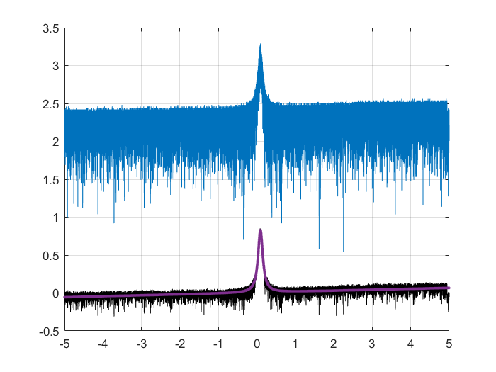
Alice Renaux | Fixed | report | lasers and optics | Optical room | new cavity | The 2-mirrors cavity has 460ppm of transmission for M1 and 10ppm for M2 which should exhibit a Finesse around 13400.
Today, we managed to lock the NKT laser (with an AOM for fast feedback) onto the cavity, and we made 5 Finesse measurements with the modulation technic : 14151, 13847, 13968, 14604, 13892 with an average around 14000 => LW = 216MHz/F ~ 16kHz.
On the plot (Frequency span 1MHz <=> Time span 10s)
blue curve : raw data
black curve : cleaned data
red curve : fitted data
| Alice Renaux wrote: |
|
Yesterday, we changed the M1 mirror to a 161185 Gamma Factory mirror of transmission 460ppm, the cavity finesse is now 13360.
We managed to lock it today.
|
|
| Attachment 1: Finesse.png
|  |
|
244
|
Tue Sep 9 21:23:11 2025 |
Alice Renaux | Fixed | report | lasers and optics | Optical room | new cavity | Yesterday, we changed the M1 mirror to a 161185 Gamma Factory mirror of transmission 460ppm, the cavity finesse is now 13360.
We managed to lock it today. |
|
243
|
Thu Sep 4 17:56:50 2025 |
Alice Renaux | Fixed | report | lasers and optics | Optical room | Finesse measurement | (Finesse 2651 is consistent with that obtained from the mirrors' transmission coefficients, which is about 3100.)
| Alice Renaux wrote: |
|
Today, with Ronic, we measured the finesse of the 2-mirror cavity witht the NKT CW laser.
We were able to perfrom the measurement only once, and the results of the measurement are attached to this note. We added sidebands to the laser spectrum peak thanks to an EOM, and we sweeped the modulation frequency on a 1MHz span around an estimated FSR of 216.63MHz in 10s. We found a 82kHz linewidth, hence a finesse of 2651.
|
|
|
242
|
Thu Sep 4 17:52:03 2025 |
Alice Renaux | Fixed | report | lasers and optics | Optical room | Finesse measurement | Today, with Ronic, we measured the finesse of the 2-mirror cavity witht the NKT CW laser.
We were able to perfrom the measurement only once, and the results of the measurement are attached to this note. We added sidebands to the laser spectrum peak thanks to an EOM, and we sweeped the modulation frequency on a 1MHz span around an estimated FSR of 216.63MHz in 10s. We found a 82kHz linewidth, hence a finesse of 2651. |
| Attachment 1: Figure_3.png
|  |
|