| ID |
Date |
Author |
Status |
Type |
Category |
Location |
Title |
|
242
|
Thu Sep 4 17:52:03 2025 |
Alice Renaux | Under Process | report | lasers and optics | Optical room | Finesse measurement | Today, with Ronic, we measured the finesse of the 2-mirror cavity witht the NKT CW laser.
We were able to perfrom the measurement only once, and the results of the measurement are attached to this note. We added sidebands to the laser spectrum peak thanks to an EOM, and we sweeped the modulation frequency on a 1MHz span around an estimated FSR of 216.63MHz in 10s. We found a 82kHz linewidth, hence a finesse of 2651. |
| Attachment 1: Figure_3.png
|  |
|
243
|
Thu Sep 4 17:56:50 2025 |
Alice Renaux | Under Process | report | lasers and optics | Optical room | Finesse measurement | (Finesse 2651 is consistent with that obtained from the mirrors' transmission coefficients, which is about 3100.)
| Alice Renaux wrote: |
|
Today, with Ronic, we measured the finesse of the 2-mirror cavity witht the NKT CW laser.
We were able to perfrom the measurement only once, and the results of the measurement are attached to this note. We added sidebands to the laser spectrum peak thanks to an EOM, and we sweeped the modulation frequency on a 1MHz span around an estimated FSR of 216.63MHz in 10s. We found a 82kHz linewidth, hence a finesse of 2651.
|
|
|
244
|
Tue Sep 9 21:23:11 2025 |
Alice Renaux | Under Process | report | lasers and optics | Optical room | new cavity | Yesterday, we changed the M1 mirror to a 161185 Gamma Factory mirror of transmission 460ppm, the cavity finesse is now 13360.
We managed to lock it today. |
|
245
|
Wed Sep 10 11:27:45 2025 |
Alice Renaux | Under Process | report | lasers and optics | Optical room | new cavity | The 2-mirrors cavity has 460ppm of transmission for M1 and 10ppm for M2 which should exhibit a Finesse around 13400.
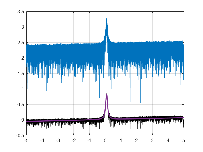
Today, we managed to lock the NKT laser (with an AOM for fast feedback) onto the cavity, and we made 5 Finesse measurements with the modulation technic : 14151, 13847, 13968, 14604, 13892 with an average around 14000 => LW = 216MHz/F ~ 16kHz.
On the plot (Frequency span 1MHz <=> Time span 10s)
blue curve : raw data
black curve : cleaned data
red curve : fitted data
| Alice Renaux wrote: |
|
Yesterday, we changed the M1 mirror to a 161185 Gamma Factory mirror of transmission 460ppm, the cavity finesse is now 13360.
We managed to lock it today.
|
|
| Attachment 1: Finesse.png
|  |
|
246
|
Wed Aug 5 11:25:41 2026 |
Ronic Chiche | Under Process | info | mechanics | lasers and optics | cabling | Optical room | Neolase amplifier installation | we have all the adaptor plugs for connecting the chiller.
so, I tested first the chiller connected in closed loop (on itself).
there is no manual, so procedure is not completely clear...
DO NOT PLUG ANYTHING BEFORE THE CHILLER ASK FOR IT
ONE MUST FOLLOW THE PROCEDURE ON THE CHILLER DISPLAY
1) if the chiller circuit is full of coolant liquid,
one must start by a System Startup -> Draining
(a trash tank and the hose will be need for emptying the circuit)
2) once the chiller circuit is empty
one must continue by System Startup -> Filling
(a clean demineralized water tank and the hose will be need for filling the circuit)
=> OK !
the chiller is able the fill and drain its circuit.
I saw the cooling water circulating in the closed loop.
|
|
247
|
Wed Aug 5 12:22:52 2026 |
Ronic Chiche | Under Process | info | mechanics | lasers and optics | cabling | Optical room | Neolase amplifier installation | now, I connected the chiller circuit to the amplifier, thanks to the adapters.
chiller IN => blue pipe => laser OUT
chiller OUT => black pipe => laser IN
after several filling and compression procedure, the flow is only 1.7Lpm and the pressure is 0.8 bar.
the temperature has been set to 20°C according to the manual operating range 18-23°C.
the flow is too low !
according to the manual, the flow should be 3-5Lpm !
a very small leakage appears if the mechanical constrains on the pipe is too high.
so, I separated the IN and OUT pipes to release this constrain and fixed the pipes to keep the position.
| Ronic Chiche wrote: |
|
we have all the adaptor plugs for connecting the chiller.
so, I tested first the chiller connected in closed loop (on itself).
there is no manual, so procedure is not completely clear...
DO NOT PLUG ANYTHING BEFORE THE CHILLER ASK FOR IT
ONE MUST FOLLOW THE PROCEDURE ON THE CHILLER DISPLAY
1) if the chiller circuit is full of coolant liquid,
one must start by a System Startup -> Draining
(a trash tank and the hose will be need for emptying the circuit)
2) once the chiller circuit is empty
one must continue by System Startup -> Filling
(a clean demineralized water tank and the hose will be need for filling the circuit)
=> OK !
the chiller is able the fill and drain its circuit.
I saw the cooling water circulating in the closed loop.
|
|
|
248
|
Wed Aug 5 13:49:49 2026 |
Ronic Chiche | Under Process | info | mechanics | lasers and optics | cabling | Optical room | Neolase amplifier installation | pipes are maybe too long ?
we can use the Darcy-Weisbach + Blasius laws (non linear laws).
I asked to ChatGPT, Claude, Mistral and MathGPT to solve it with these parameters :
L ~ 3m
D = 1 cm
water at 20°C
dP = 0.7 bar
they all found ~ 22-23L/min
so, the tube length should not be the problem... to be investiguated.
| Ronic Chiche wrote: |
|
now, I connected the chiller circuit to the amplifier, thanks to the adapters.
chiller IN => blue pipe => laser OUT
chiller OUT => black pipe => laser IN
after several filling and compression procedure, the flow is only 1.7Lpm and the pressure is 0.8 bar.
the temperature has been set to 20°C according to the manual operating range 18-23°C.
the flow is too low !
according to the manual, the flow should be 3-5Lpm !
a very small leakage appears if the mechanical constrains on the pipe is too high.
so, I separated the IN and OUT pipes to release this constrain and fixed the pipes to keep the position.
| Ronic Chiche wrote: |
|
we have all the adaptor plugs for connecting the chiller.
so, I tested first the chiller connected in closed loop (on itself).
there is no manual, so procedure is not completely clear...
DO NOT PLUG ANYTHING BEFORE THE CHILLER ASK FOR IT
ONE MUST FOLLOW THE PROCEDURE ON THE CHILLER DISPLAY
1) if the chiller circuit is full of coolant liquid,
one must start by a System Startup -> Draining
(a trash tank and the hose will be need for emptying the circuit)
2) once the chiller circuit is empty
one must continue by System Startup -> Filling
(a clean demineralized water tank and the hose will be need for filling the circuit)
=> OK !
the chiller is able the fill and drain its circuit.
I saw the cooling water circulating in the closed loop.
|
|
|
|
249
|
Thu Aug 6 14:49:32 2026 |
Ronic Chiche | Under Process | info | mechanics | lasers and optics | cabling | Optical room | Neolase amplifier installation | I drained the chiller to install again the short pipe (< 1m) in closed loop.
then, I filled again the chiller and did the compression process to obtain 1bar.
in that case, the flow measured by the chiller is correct about 5.8Lpm.
PS : the correct length for the previous calculation is 6m (2x 3m) and not 3m...
in that case, the flow should be ~ 15Lpm (and not 22 Lpm)
| )Ronic Chiche wrote: |
|
pipes are maybe too long ?
we can use the Darcy-Weisbach + Blasius laws (non linear laws).
I asked to ChatGPT, Claude, Mistral and MathGPT to solve it with these parameters :
L ~ 3m
D = 1 cm
water at 20°C
dP = 0.7 bar
they all found ~ 22-23L/min
so, the tube length should not be the problem... to be investiguated.
| Ronic Chiche wrote: |
|
now, I connected the chiller circuit to the amplifier, thanks to the adapters.
chiller IN => blue pipe => laser OUT
chiller OUT => black pipe => laser IN
after several filling and compression procedure, the flow is only 1.7Lpm and the pressure is 0.8 bar.
the temperature has been set to 20°C according to the manual operating range 18-23°C.
the flow is too low !
according to the manual, the flow should be 3-5Lpm !
a very small leakage appears if the mechanical constrains on the pipe is too high.
so, I separated the IN and OUT pipes to release this constrain and fixed the pipes to keep the position.
| Ronic Chiche wrote: |
|
we have all the adaptor plugs for connecting the chiller.
so, I tested first the chiller connected in closed loop (on itself).
there is no manual, so procedure is not completely clear...
DO NOT PLUG ANYTHING BEFORE THE CHILLER ASK FOR IT
ONE MUST FOLLOW THE PROCEDURE ON THE CHILLER DISPLAY
1) if the chiller circuit is full of coolant liquid,
one must start by a System Startup -> Draining
(a trash tank and the hose will be need for emptying the circuit)
2) once the chiller circuit is empty
one must continue by System Startup -> Filling
(a clean demineralized water tank and the hose will be need for filling the circuit)
=> OK !
the chiller is able the fill and drain its circuit.
I saw the cooling water circulating in the closed loop.
|
|
|
|
|
250
|
Thu Aug 6 15:12:49 2026 |
Ronic Chiche | Under Process | info | mechanics | lasers and optics | cabling | Optical room | Neolase amplifier installation | now, I installed the long pipes (2x 3m) in closed loop (without the amplifier connected), but the exact ones used to connect the laser, with the same pipe adapters.
after the compression process, the chiller works at 0.9 bar and the measured flow is 4.7Lpm.
so, it's still OK !
after a long time, I observed a small leakage on the "male" adapter on the amplifier side.
| Ronic Chiche wrote: |
|
I drained the chiller to install again the short pipe (< 1m) in closed loop.
then, I filled again the chiller and did the compression process to obtain 1bar.
in that case, the flow measured by the chiller is correct about 5.8Lpm.
PS : the correct length for the previous calculation is 6m (2x 3m) and not 3m...
in that case, the flow should be ~ 15Lpm (and not 22 Lpm)
| )Ronic Chiche wrote: |
|
pipes are maybe too long ?
we can use the Darcy-Weisbach + Blasius laws (non linear laws).
I asked to ChatGPT, Claude, Mistral and MathGPT to solve it with these parameters :
L ~ 3m
D = 1 cm
water at 20°C
dP = 0.7 bar
they all found ~ 22-23L/min
so, the tube length should not be the problem... to be investiguated.
| Ronic Chiche wrote: |
|
now, I connected the chiller circuit to the amplifier, thanks to the adapters.
chiller IN => blue pipe => laser OUT
chiller OUT => black pipe => laser IN
after several filling and compression procedure, the flow is only 1.7Lpm and the pressure is 0.8 bar.
the temperature has been set to 20°C according to the manual operating range 18-23°C.
the flow is too low !
according to the manual, the flow should be 3-5Lpm !
a very small leakage appears if the mechanical constrains on the pipe is too high.
so, I separated the IN and OUT pipes to release this constrain and fixed the pipes to keep the position.
| Ronic Chiche wrote: |
|
we have all the adaptor plugs for connecting the chiller.
so, I tested first the chiller connected in closed loop (on itself).
there is no manual, so procedure is not completely clear...
DO NOT PLUG ANYTHING BEFORE THE CHILLER ASK FOR IT
ONE MUST FOLLOW THE PROCEDURE ON THE CHILLER DISPLAY
1) if the chiller circuit is full of coolant liquid,
one must start by a System Startup -> Draining
(a trash tank and the hose will be need for emptying the circuit)
2) once the chiller circuit is empty
one must continue by System Startup -> Filling
(a clean demineralized water tank and the hose will be need for filling the circuit)
=> OK !
the chiller is able the fill and drain its circuit.
I saw the cooling water circulating in the closed loop.
|
|
|
|
|
|
251
|
Fri Aug 7 10:59:52 2026 |
Ronic Chiche | Under Process | info | mechanics | lasers and optics | cabling | Optical room | Neolase amplifier installation | I cut a small part of the black pipe on the amplifier side (could it be slightly deformed by a try with an other type of adapter ?), with the dedicated tool, changed the adapter and plugged it more firmly in the pipe (pipe deeply inserted in the adapter).
it seems, there is no more leakage.
measured pressure and flow are 0.9 bar and 4.7Lpm => OK without amplifier.
| Ronic Chiche wrote: |
|
now, I installed the long pipes (2x 3m) in closed loop (without the amplifier connected), but the exact ones used to connect the laser, with the same pipe adapters.
after the compression process, the chiller works at 0.9 bar and the measured flow is 4.7Lpm.
so, it's still OK !
after a long time, I observed a small leakage on the "male" adapter on the amplifier side.
| Ronic Chiche wrote: |
|
I drained the chiller to install again the short pipe (< 1m) in closed loop.
then, I filled again the chiller and did the compression process to obtain 1bar.
in that case, the flow measured by the chiller is correct about 5.8Lpm.
PS : the correct length for the previous calculation is 6m (2x 3m) and not 3m...
in that case, the flow should be ~ 15Lpm (and not 22 Lpm)
| )Ronic Chiche wrote: |
|
pipes are maybe too long ?
we can use the Darcy-Weisbach + Blasius laws (non linear laws).
I asked to ChatGPT, Claude, Mistral and MathGPT to solve it with these parameters :
L ~ 3m
D = 1 cm
water at 20°C
dP = 0.7 bar
they all found ~ 22-23L/min
so, the tube length should not be the problem... to be investiguated.
| Ronic Chiche wrote: |
|
now, I connected the chiller circuit to the amplifier, thanks to the adapters.
chiller IN => blue pipe => laser OUT
chiller OUT => black pipe => laser IN
after several filling and compression procedure, the flow is only 1.7Lpm and the pressure is 0.8 bar.
the temperature has been set to 20°C according to the manual operating range 18-23°C.
the flow is too low !
according to the manual, the flow should be 3-5Lpm !
a very small leakage appears if the mechanical constrains on the pipe is too high.
so, I separated the IN and OUT pipes to release this constrain and fixed the pipes to keep the position.
| Ronic Chiche wrote: |
|
we have all the adaptor plugs for connecting the chiller.
so, I tested first the chiller connected in closed loop (on itself).
there is no manual, so procedure is not completely clear...
DO NOT PLUG ANYTHING BEFORE THE CHILLER ASK FOR IT
ONE MUST FOLLOW THE PROCEDURE ON THE CHILLER DISPLAY
1) if the chiller circuit is full of coolant liquid,
one must start by a System Startup -> Draining
(a trash tank and the hose will be need for emptying the circuit)
2) once the chiller circuit is empty
one must continue by System Startup -> Filling
(a clean demineralized water tank and the hose will be need for filling the circuit)
=> OK !
the chiller is able the fill and drain its circuit.
I saw the cooling water circulating in the closed loop.
|
|
|
|
|
|
|
252
|
Fri Aug 7 11:41:17 2026 |
Ronic Chiche | Under Process | info | mechanics | lasers and optics | cabling | Optical room | Neolase amplifier installation | as soon as I connect the amplifier to the pipes, the flow decreases to 1.7Lpm.
and the filling process is very long and noisy, as there was something blocking the filling process...
| Ronic Chiche wrote: |
|
I cut a small part of the black pipe on the amplifier side (could it be slightly deformed by a try with an other type of adapter ?), with the dedicated tool, changed the adapter and plugged it more firmly in the pipe (pipe deeply inserted in the adapter).
it seems, there is no more leakage.
measured pressure and flow are 0.9 bar and 4.7Lpm => OK without amplifier.
| Ronic Chiche wrote: |
|
now, I installed the long pipes (2x 3m) in closed loop (without the amplifier connected), but the exact ones used to connect the laser, with the same pipe adapters.
after the compression process, the chiller works at 0.9 bar and the measured flow is 4.7Lpm.
so, it's still OK !
after a long time, I observed a small leakage on the "male" adapter on the amplifier side.
| Ronic Chiche wrote: |
|
I drained the chiller to install again the short pipe (< 1m) in closed loop.
then, I filled again the chiller and did the compression process to obtain 1bar.
in that case, the flow measured by the chiller is correct about 5.8Lpm.
PS : the correct length for the previous calculation is 6m (2x 3m) and not 3m...
in that case, the flow should be ~ 15Lpm (and not 22 Lpm)
| )Ronic Chiche wrote: |
|
pipes are maybe too long ?
we can use the Darcy-Weisbach + Blasius laws (non linear laws).
I asked to ChatGPT, Claude, Mistral and MathGPT to solve it with these parameters :
L ~ 3m
D = 1 cm
water at 20°C
dP = 0.7 bar
they all found ~ 22-23L/min
so, the tube length should not be the problem... to be investiguated.
| Ronic Chiche wrote: |
|
now, I connected the chiller circuit to the amplifier, thanks to the adapters.
chiller IN => blue pipe => laser OUT
chiller OUT => black pipe => laser IN
after several filling and compression procedure, the flow is only 1.7Lpm and the pressure is 0.8 bar.
the temperature has been set to 20°C according to the manual operating range 18-23°C.
the flow is too low !
according to the manual, the flow should be 3-5Lpm !
a very small leakage appears if the mechanical constrains on the pipe is too high.
so, I separated the IN and OUT pipes to release this constrain and fixed the pipes to keep the position.
| Ronic Chiche wrote: |
|
we have all the adaptor plugs for connecting the chiller.
so, I tested first the chiller connected in closed loop (on itself).
there is no manual, so procedure is not completely clear...
DO NOT PLUG ANYTHING BEFORE THE CHILLER ASK FOR IT
ONE MUST FOLLOW THE PROCEDURE ON THE CHILLER DISPLAY
1) if the chiller circuit is full of coolant liquid,
one must start by a System Startup -> Draining
(a trash tank and the hose will be need for emptying the circuit)
2) once the chiller circuit is empty
one must continue by System Startup -> Filling
(a clean demineralized water tank and the hose will be need for filling the circuit)
=> OK !
the chiller is able the fill and drain its circuit.
I saw the cooling water circulating in the closed loop.
|
|
|
|
|
|
|
|