| ID |
Date |
Author |
Status |
Type |
Category |
Location |
Title |
|
226
|
Fri Nov 29 12:06:05 2024 |
Alice Renaux | Fixed | info | lasers and optics | Optical room | Menhir 160MHz laser |
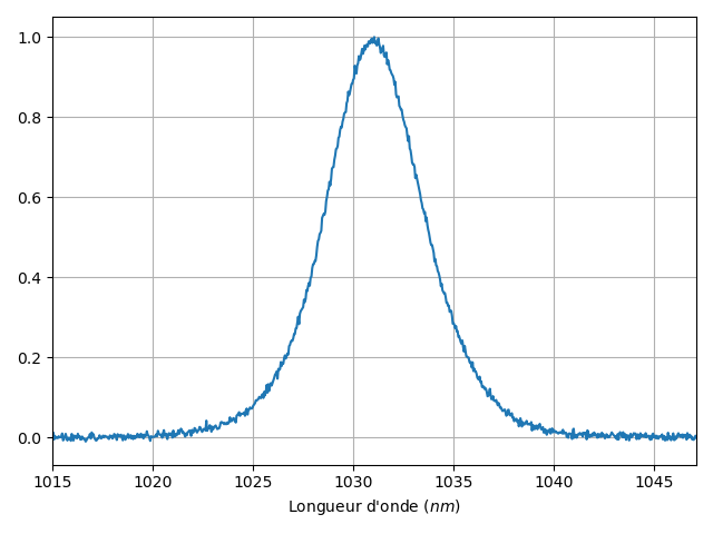
The Menhir 160MHz has been put back in place on the CELIA amplifier setup. Its output power is measured to be 150-160mW with an attenuator as expected. Its spectrum is available in "spectre_avant_cvbg.xlsx" and "spectre_avant_cvbg.png".
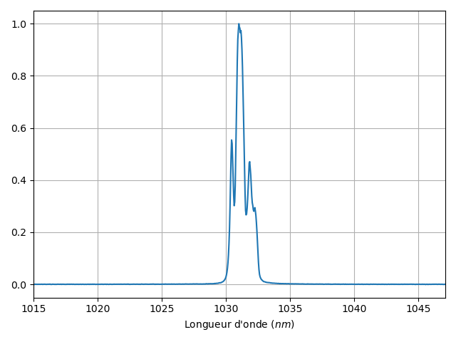
The pulses are stretched by means of a CVBG. Their spectrum is available in "spectre_apres_cvbg.xlsx" and "spectre_apres_cvbg.png".
The laser is coupled into an optical fiber with an output power of 11.5mW for a 32mW input.
|
| Attachment 1: spectre_avant_cvbg.xlsx
|
| Attachment 2: spectre_apres_cvbg.xlsx
|
| Attachment 3: spectre_avant_cvbg.png
|
 |
| Attachment 4: spectre_apres_cvbg.png
|
 |
|
227
|
Fri Nov 29 16:50:04 2024 |
Alice Renaux | Fixed | info | lasers and optics | Optical room | Menhir 216MHz laser |
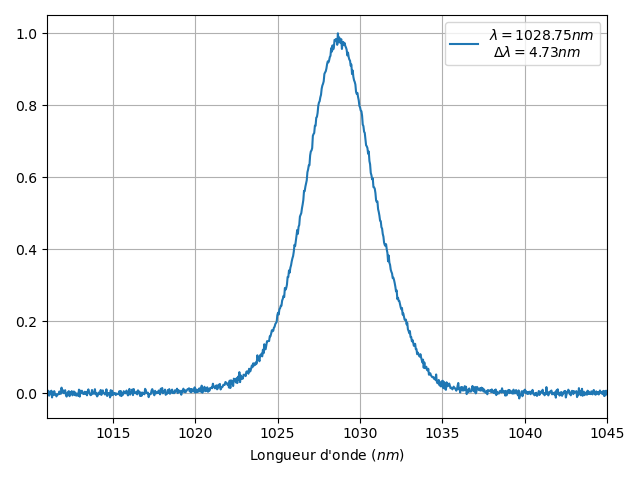
The Menhir 216MHz laser has been put back in place on the cavity table. Its output power is measured to be 160mW with an attenuator. Its spectrum is available in "spectre.xlsx" and "spectre.png". The main wavelength is a bit shorter (1028.75nm) and the spectrum a bit narrower (4.73nm) than expected.
|
| Attachment 1: spectre.xlsx
|
| Attachment 2: spectre.png
|
 |
|
230
|
Mon Dec 16 10:20:56 2024 |
Ronic Chiche | Fixed | issue | lasers and optics | Optical room | CELIA 100W laser amplifier repair |
friday morning, we add a zoom call with Jerome Lhermite about the amplifier repair.
he approximately confirmed the amplifier scheme from the Loic thesis.
he suggested to:
1) identify the circulator ports.
they have some tapes with text written on them.
the goal is to understand if it is still used in the present setup and if a CFBG could still be connected to it (and from which one end could be the fiber seen "broken").
2) use the 5% output tap of the amplifier to check if some light is outed if the input or circulator fibers are injected with 1st stage switched ON or OFF.
3) follow the "broken" fiber to check to which element it is connected to => we should need to unroll the fibers in the bottom "fiber cassette"... :-(
| Ronic Chiche wrote: |
|
this afternoon, we saw some electric cables badly connected to their power supply.
we fixed it by soldering them together and screwing the result to the power supply.
(see 1st image)
we lift the plate of the 1st stage and we check for optical leakage in the fibers (see 2nd image + picture of the top part of the cassette).
(Aurélien took several images)
without the 1st stage amplification, we saw some lealage only in the bottom part of the "optical cassette".
light was scattered mostly from one side (2 spots) and we saw also very weak scattering in the other directions.
with the 1st stage amplification, we clearly saw the losses from the bent fibers inside the top part of the cassette => it's a good sign.
but after the 5%-10% coupler (the one used for the diagnostic of the power to allow the use of the 2nd stage), we don't see any losses, which means there is no light in this part !
the fiber break could be in between...
Aurélien should send the images to Jérome to get a diagnostic.
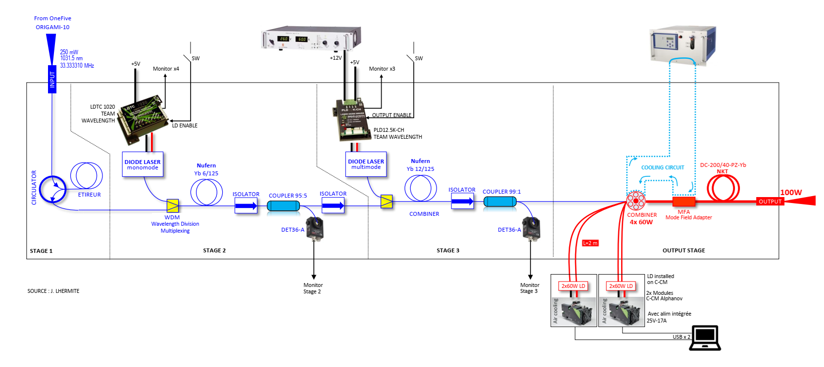
the old schematic is attached but it has been modified in the Loic Thesis (p. 165)
we identified the black optics components as 2 isolators (AFW-PISO-30-1W-FB) and 1 circulator (AFW-CIR-PM-30) from AFW technologies.
| Ronic Chiche wrote: |
|
this morning with Alice, we sent the Menhir 160MHz injected in a fiber (with 6mW at the end of a long fiber) into the laser amplifier, to look for leakage or damage in the first stages of the amplifier (the amplifier is totally off).
first of all, we checked for light scattering around the laser crate with a sensitive optical card => nothing
and then, we checked for light scattering inside the laser crate with an optical viewer => we just saw 1 or 2 small spots located at the end of an optical element at the 2nd stage level.
but it's difficult to understand the optical path and know the different elements with the 1st stage still in place.
we think it is mandatory to open the top of the crate and lift the 1st stage to have a better look inside the optical parts which are at the 2nd and 3rd stage levels:
we could remove the front side of the crate without any damage to any fibers in the crate.
we just saw 1 fiber, glued to an optical element on the 2nd stage, and going to the 3rd stage.
the 1st stage is just an electronics parts stage which seems easy to be removed.
... to be discussed...
|
|
|
| Attachment 1: Sans_titre.png
|
 |
|
234
|
Tue May 27 18:12:22 2025 |
Alice Renaux | Fixed | report | lasers and optics | Optical room | 2-mirror cavity alignment |
Yesterday and today, I replaced the OEWaves CW laser with the NKT CW laser. Its screen does not display anything, so it has to be operated through the GraphiK software.
I then re-aligned the cavity with a new adjustment adaptation tool between the mirror mounts and the irises.
The motor positions are :
- 1 : 3.354420 mm
- 3 : 2.128850 mm
- 4 : 3.468480 mm
- 5 : 3.157300 mm
I then connected the LaseLock module to scan the NKT laser wavelength on a roughly 0-10 V range at a 2Hz rate, so that it could match the cavity's resonance frequency.
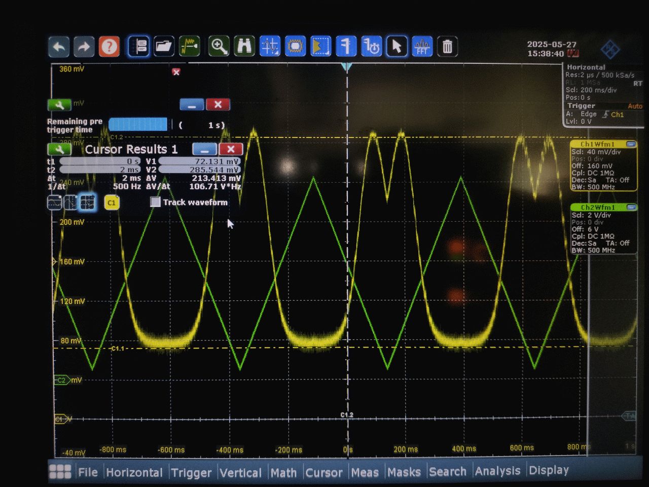
Without optimizing the injection, I monitored the transmitted power with a photodiode paired with an amplifier. The pictures are available through this link : https://box.in2p3.fr/s/TGgwkKgYik7MyqW, and an example picture is attached. Their timestamp is in their filenames, and it seems that the transmission varies quite a lot on a ≈10 s scale, and these variations seem to be periodic on a ≈1 minute scale. The peaks seem weirdly wide, almost up to 100-200 MHz (≈FSR). |
| Attachment 1: IMG20250527160111.jpg
|
 |
|
235
|
Wed May 28 10:55:15 2025 |
Alice Renaux | Fixed | report | lasers and optics | Optical room | 2-mirror cavity alignment |
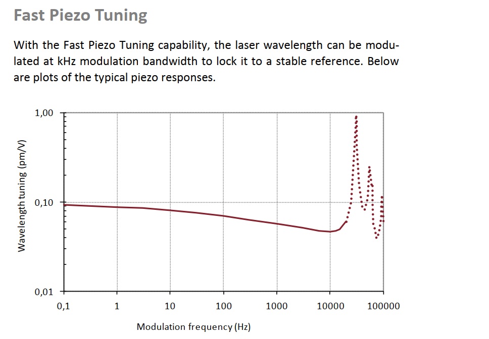
The NKT laser PZT sensitivity is ~0.09pm/V of wavelength variation, which is equivalent to ~ 25MHz/V
So, the full range of the scan is roughly 250MHz (more than a FSR) for 10V.
It seems impossible to get such large resonances unless the Finesse is very low => let's try to change M1 by a spare GammaFactory plan or 10m ROC mirror.
| Alice Renaux wrote: |
|
Yesterday and today, I replaced the OEWaves CW laser with the NKT CW laser. Its screen does not display anything, so it has to be operated through the GraphiK software.
I then re-aligned the cavity with a new adjustment adaptation tool between the mirror mounts and the irises.
The motor positions are :
- 1 : 3.354420 mm
- 3 : 2.128850 mm
- 4 : 3.468480 mm
- 5 : 3.157300 mm
I then connected the LaseLock module to scan the NKT laser wavelength on a roughly 0-10 V range at a 2Hz rate, so that it could match the cavity's resonance frequency.
Without optimizing the injection, I monitored the transmitted power with a photodiode paired with an amplifier. The pictures are available through this link : https://box.in2p3.fr/s/TGgwkKgYik7MyqW, and an example picture is attached. Their timestamp is in their filenames, and it seems that the transmission varies quite a lot on a ≈10 s scale, and these variations seem to be periodic on a ≈1 minute scale. The peaks seem weirdly wide, almost up to 100-200 MHz (≈FSR).
|
|
| Attachment 1: Sans_titre.jpg
|
 |
|
236
|
Wed May 28 18:27:27 2025 |
Alice Renaux | Fixed | report | lasers and optics | Optical room | 2-mirror cavity full setup |
Today with Ronic, we changed the FP cavity's mirrors to Layertek (Gamma Factory) mirrors :
- M1 : n°161186 --> fused silica, unknown absorption, unknown diffusion, T1=2500ppm transmission planar mirror ;
- M2 : n°161182 --> fused silica, unknown absorption, unknown diffusion, T2=10ppm transmission, 5m ROC mirror.
RTL (round-trip losses) ~ 2500 + 10 ppm (we forget the unknown parameters for absorption and diffusion).
The maximal finesse we could expect is thus F=π([(1-T1)(1-T2)]^(1/4))/(1-[(1-T1)(1-2)]^(1/2)) ~ 2*pi /RTL ≈ 2500 assuming no absorption and no scattering.
The FP cavity's FSR is ≈ 216 MHz given its length.
We managed to see some optical beating on the FP cavity's mirrors and to reach the fundamental transverse mode of the FP cavity by adjusting the injection mirrors, but when scanning the laser's wavelength, some higher-order modes appear and the fundamental mode is reached when the voltage applied to the piezoelectric actuator of the laser's cavity is ≈0V. The actuator is not meant to work with negative voltages, so we translated one of the FP cavity's mirrors so that the fundamental transverse mode's resonance frequency is in the middle of the voltage range.
We also removed the D-shaped mirrors, as they are only useful when working with high power. |
|
237
|
Fri Jun 13 20:10:00 2025 |
Alice Renaux | Fixed | report | lasers and optics | Optical room | Damaged mirrors test |
Today with Dorian we tested three mirrors with which we previously haven't been able to obtain any resonance or optical beating :
- C16111/11 : The mirror looks normal under a microscope, apart from a few inclusions and maybe a small scratch towards the edge. We tested it with a 161186 M1 mirror and we weren't able to obtain any optical beating on the cavity's mirrors or resonance.
- 161185 (1) : The mirror looks normal with the naked eye. We tested it with a 161182 M2 mirror and we were able to notice some optical beating on the cavity's mirrors as well as small resonance peaks and a higher-order transverse mode.
- 161185 (2) : The mirror shows some damage on the substrate side (not the coated side). We tested it with a 161186 M2 mirror and we were able to notice some optical beating on the cavity's mirrors as well as huge resonance peaks and a Gaussian transverse mode.
The updated recap file is available here, as well as a few pictures. |
|
239
|
Thu Aug 28 15:29:00 2025 |
Alice Renaux | Fixed | report | lasers and optics | Optical room | 2-mirror cavity locking |
In June, we encountered some problems regarding the transmission and error signals (see images here), looking as if the laser was switched off before the cavity was filled.
Aurélien, Ronic and I discussed this on 08/27, resulting in a list of tests to perform. We :
- checked the mirrors' thickness (maybe there was some mechanical stress if they were too thick). The mirrors' thickness is 6.35mm (1/4 inch) and is consistent with the mounts size ;
- checked the mirrors' mounts' screws' tightening (maybe the mirrors were either moving if the screws were not tight enough or some mechanical stress if they were too tight). We tightened the mirrors' mounts' upper screws.
Next thing we did with Ronic was check if the error signal depended on the modulation/demodulation relative phase, which was not the case, but it should have.
Ronic added a quarter waveplate before the half waveplate in the injection system.
Today, on 08/29, the succession of the higher-order transverse modes when scanning the seeder laser's piezoelectric actuator's voltage to scan the seeder laser's optical frequency seemed a bit strange, so we checked the resonance frequencies of several occurrences of the same transverse mode :
- (0, 0) : @ -0.4V and 6.0V ;
- (1, 0) and (0, 1) : @0.5V and 6.9V.
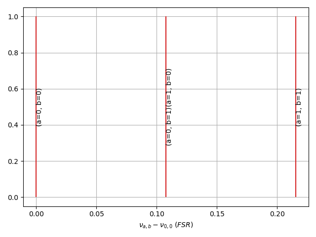
In both cases, several occurrences were separated by about 6.4V, which corresponds to the voltage difference to scan a full FSR. The spacing between (0, 0) and (1, 0)/(0, 1) is then about 0.14*FSR.
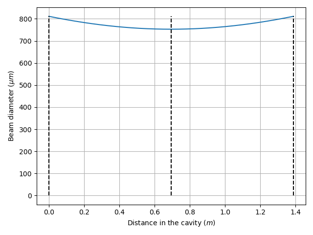
I checked this by writing a small piece of Python code to calculate the cavity's fundamental transverse mode and its Rayleigh length, which is displayed in Figure 1, and then by calculating the resonance frequencies wrt the (0, 0) resonance frequency for the (1, 0), (0, 1) and (1, 1) transverse modes, which is displayed in Figure 2, with the following formula: $\nu_{p, n, m}=(p+\frac{(n+\frac{1}{2})\arctan(\frac{2L_{\text{cav}}}{z_{\text{R}}})+(m+\frac{1}{2})\arctan(\frac{2L_{\text{cav}}}{z_{\text{R}}})}{2\pi})\times\text{FSR}$ for a $p$ longitudinal and ($n$, $m$) transverse mode. Here, $p=1$. The spacing betwen (0, 0) and (1, 0)/(0, 1) is about 0.11*FSR, making the previous observation consistent with the calculation. Everything seems normal.
Ronic also increased the EOM modulation voltage, increasing the modulation depth for the generation of the error signal (from 100mV RMS to 300mV RMS), making the error signal depend on the modulation/demodulation relative phase, as it should. He managed to lock the laser onto the cavity for about 1s at a time.
Next steps are to optimize the PID parameters and to add a low-pass filter/AOM to cut the higher frequencies off and improve the feedback loop. |
| Attachment 1: Figure_1.png
|
 |
| Attachment 2: Figure_2.png
|
 |
|
240
|
Wed Sep 3 18:10:34 2025 |
Alice Renaux | Fixed | report | lasers and optics | Optical room | Successful lock (finally !) |
Today, with Ronic, we managed to get a successful lock with the NKT laser by setting up a new PDH box from scratch (photodiode + amplifer + mixer).
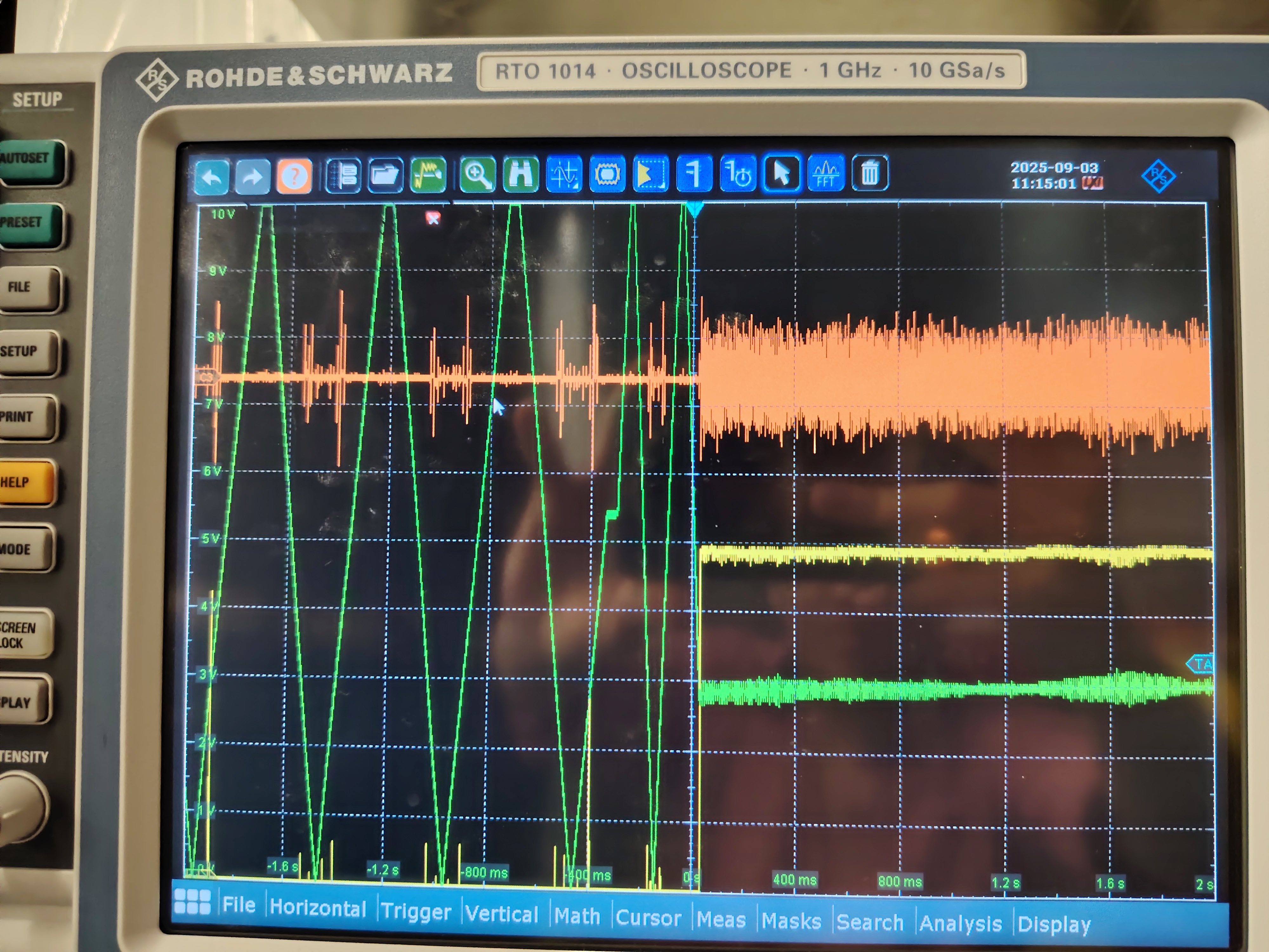
Me measured the injected power (5.4mW) and the transmitted power (33µW) after a wedge (92% transmission) and a 7ppm transmission mirror, so the intracavity power was 5.1W. We have a 950 enhancement factor for a 3100 finesse cavity, so a nominal enhancement factor of 2500. The lock was very stable, as shown in the attached picture (yellow signal is the transmitted power, orange signal is the error signal and green signal is the voltage sent from the Laselock module to the pizeoelectric actuator of the NKT laser cavity).
Then, we added a second EOM in order to perform a finesse measurement, but we weren't able to inject more than 3mW at full laser power in the cavity or to lock the laser onto the cavity. |
| Attachment 1: IMG_20250903_113758.jpg
|
 |
|
242
|
Thu Sep 4 17:52:03 2025 |
Alice Renaux | Fixed | report | lasers and optics | Optical room | Finesse measurement |
Today, with Ronic, we measured the finesse of the 2-mirror cavity witht the NKT CW laser.
We were able to perfrom the measurement only once, and the results of the measurement are attached to this note. We added sidebands to the laser spectrum peak thanks to an EOM, and we sweeped the modulation frequency on a 1MHz span around an estimated FSR of 216.63MHz in 10s. We found a 82kHz linewidth, hence a finesse of 2651. |
| Attachment 1: Figure_3.png
|
 |
|
243
|
Thu Sep 4 17:56:50 2025 |
Alice Renaux | Fixed | report | lasers and optics | Optical room | Finesse measurement |
(Finesse 2651 is consistent with that obtained from the mirrors' transmission coefficients, which is about 3100.)
| Alice Renaux wrote: |
|
Today, with Ronic, we measured the finesse of the 2-mirror cavity witht the NKT CW laser.
We were able to perfrom the measurement only once, and the results of the measurement are attached to this note. We added sidebands to the laser spectrum peak thanks to an EOM, and we sweeped the modulation frequency on a 1MHz span around an estimated FSR of 216.63MHz in 10s. We found a 82kHz linewidth, hence a finesse of 2651.
|
|
|
244
|
Tue Sep 9 21:23:11 2025 |
Alice Renaux | Fixed | report | lasers and optics | Optical room | new cavity |
Yesterday, we changed the M1 mirror to a 161185 Gamma Factory mirror of transmission 460ppm, the cavity finesse is now 13360.
We managed to lock it today. |
|
245
|
Wed Sep 10 11:27:45 2025 |
Alice Renaux | Fixed | report | lasers and optics | Optical room | new cavity |
The 2-mirrors cavity has 460ppm of transmission for M1 and 10ppm for M2 which should exhibit a Finesse around 13400.
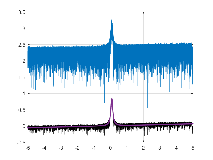
Today, we managed to lock the NKT laser (with an AOM for fast feedback) onto the cavity, and we made 5 Finesse measurements with the modulation technic : 14151, 13847, 13968, 14604, 13892 with an average around 14000 => LW = 216MHz/F ~ 16kHz.
On the plot (Frequency span 1MHz <=> Time span 10s)
blue curve : raw data
black curve : cleaned data
red curve : fitted data
| Alice Renaux wrote: |
|
Yesterday, we changed the M1 mirror to a 161185 Gamma Factory mirror of transmission 460ppm, the cavity finesse is now 13360.
We managed to lock it today.
|
|
| Attachment 1: Finesse.png
|
 |
|
257
|
Thu Aug 27 11:08:44 2026 |
Ronic Chiche | Fixed | info | lasers and optics | Optical room | fiber patch cables attenuation measurements |
attenuation with 1 mating sleeve :
green jacket fiber : -0.4 dB
blue jacket fiber N°1 : -0.5 dB
blue jacket fiber N°2 : -0.27 dB
blue jacket fiber N°3 : -0.13 dB
blue jacket fiber N°4 : -1.4 dB
we should try to polish at least the fiber 4 which seems faulty.
|
|
258
|
Thu Aug 27 11:13:07 2026 |
Ronic Chiche | Under Process | info | lasers and optics | Optical room | Menhir oscillator phase noise measurement |
with Alice, we installed the Menhir 160MHz oscillator on a breadboad placed on top of 4 damped feet around the amplifier.
we will do an heterodyne phase noise measurement vs the CW OEwaves oscillator.
the power at the output of the Menhir oscillator is about 150mW.
after injection in the fiber (N°3 blue jacket), we got about 75mW.
we installed the 2->1 coupler to make the beating.
BE CAREFUL, the coupler is polarization sensitive, so we add a half waveplate in the Menhir path to adust the polarization on the coupler, otherwise the output power can be very low.
the coupler attenuation is ~ 3.5dB on both inputs.
the OEwaves power is ~16mW at the input and we measured ~7mW at the output of the coupler for this channel.
the Menhir fiber coupled power is ~75mW and we measured ~26mW at the output of the coupler for this channel.
|
|
259
|
Mon Aug 31 15:14:04 2026 |
Ronic Chiche | Under Process | info | lasers and optics | Optical room | Menhir oscillator phase noise measurement |
measurements made with Alice:
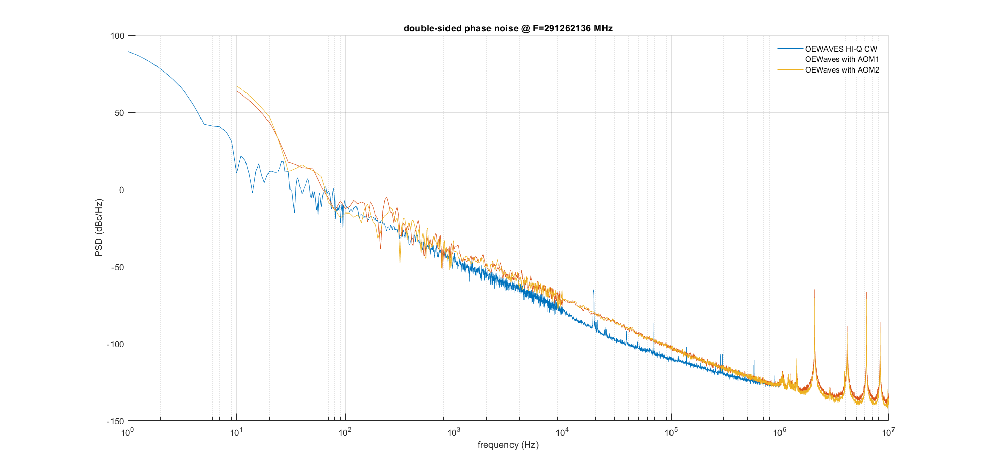
comparison between the CW OEwaves oscillator phase noise measured last week (2 measurements done with AOM, in red and orange) with the one made in 2022 (without AOM, in blue).
one observes a degradation of the performance of the oscillator by ~10dB in the region of interest 100Hz-100kHz
| Ronic Chiche wrote: |
|
with Alice, we installed the Menhir 160MHz oscillator on a breadboad placed on top of 4 damped feet around the amplifier.
we will do an heterodyne phase noise measurement vs the CW OEwaves oscillator.
the power at the output of the Menhir oscillator is about 150mW.
after injection in the fiber (N°3 blue jacket), we got about 75mW.
we installed the 2->1 coupler to make the beating.
BE CAREFUL, the coupler is polarization sensitive, so we add a half waveplate in the Menhir path to adust the polarization on the coupler, otherwise the output power can be very low.
the coupler attenuation is ~ 3.5dB on both inputs.
the OEwaves power is ~16mW at the input and we measured ~7mW at the output of the coupler for this channel.
the Menhir fiber coupled power is ~75mW and we measured ~26mW at the output of the coupler for this channel.
|
|
| Attachment 1: CW_OEwaves_phase_noise_comparison.png
|
 |
|
260
|
Mon Aug 31 16:15:46 2026 |
Ronic Chiche | Under Process | info | lasers and optics | Optical room | Menhir oscillator phase noise measurement |
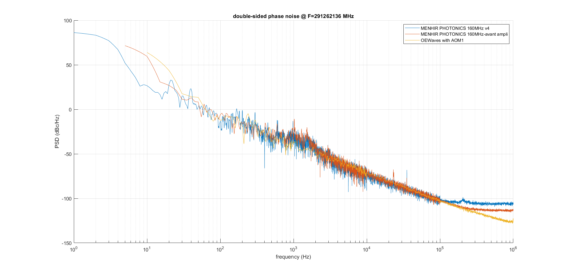
comparison of the Menhir 160MHz phase noise with the CW reference.
- in blue, the oscillators are placed on top of an aluminium breadboard, placed directly on an optical table (measurement made in june)
- in red, the oscillators are placed on top of an aluminium breadboard, placed directly on top of 4 feet with Thorlabs AV4/M Sorbothane dampers, above the NeoLase amplifier (measurement made last week)
=> similar behavior with phase noise increasing around 1kHz, compared to the reference.
| Ronic Chiche wrote: |
|
measurements made with Alice:
comparison between the CW OEwaves oscillator phase noise measured last week (2 measurements done with AOM, in red and orange) with the one made in 2022 (without AOM, in blue).
one observes a degradation of the performance of the oscillator by ~10dB in the region of interest 100Hz-100kHz
| Ronic Chiche wrote: |
|
with Alice, we installed the Menhir 160MHz oscillator on a breadboad placed on top of 4 damped feet around the amplifier.
we will do an heterodyne phase noise measurement vs the CW OEwaves oscillator.
the power at the output of the Menhir oscillator is about 150mW.
after injection in the fiber (N°3 blue jacket), we got about 75mW.
we installed the 2->1 coupler to make the beating.
BE CAREFUL, the coupler is polarization sensitive, so we add a half waveplate in the Menhir path to adust the polarization on the coupler, otherwise the output power can be very low.
the coupler attenuation is ~ 3.5dB on both inputs.
the OEwaves power is ~16mW at the input and we measured ~7mW at the output of the coupler for this channel.
the Menhir fiber coupled power is ~75mW and we measured ~26mW at the output of the coupler for this channel.
|
|
|
| Attachment 1: Mehnir_PN_plots.png
|
 |
|
261
|
Mon Aug 31 16:28:31 2026 |
Ronic Chiche | Under Process | info | lasers and optics | Optical room | Menhir oscillator phase noise measurement |
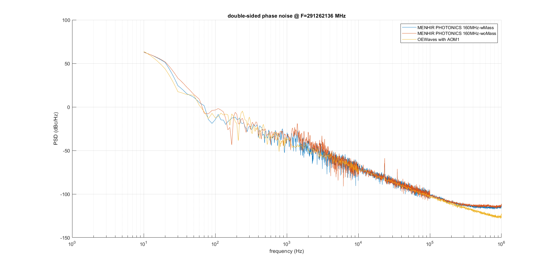
after the previous measurement, we installed similar dampers, than the ones used belows the aluminium breadboard, placed below the 4 Menhir 160MHz "feet", in contact with the aluminium breadboard.
- in red, phase noise measurement with the Sorbothane feet below the Menhir laser and below the aluminium breadboard.
- in blue,same measurment with an additionnal heavy mass placed in the middle of the breadboard.
| Ronic Chiche wrote: |
|
comparison of the Menhir 160MHz phase noise with the CW reference.
- in blue, the oscillators are placed on top of an aluminium breadboard, placed directly on an optical table (measurement made in june)
- in red, the oscillators are placed on top of an aluminium breadboard, placed directly on top of 4 feet with Thorlabs AV4/M Sorbothane dampers, above the NeoLase amplifier (measurement made last week)
=> similar behavior with phase noise increasing around 1kHz, compared to the reference.
| Ronic Chiche wrote: |
|
measurements made with Alice:
comparison between the CW OEwaves oscillator phase noise measured last week (2 measurements done with AOM, in red and orange) with the one made in 2022 (without AOM, in blue).
one observes a degradation of the performance of the oscillator by ~10dB in the region of interest 100Hz-100kHz
| Ronic Chiche wrote: |
|
with Alice, we installed the Menhir 160MHz oscillator on a breadboad placed on top of 4 damped feet around the amplifier.
we will do an heterodyne phase noise measurement vs the CW OEwaves oscillator.
the power at the output of the Menhir oscillator is about 150mW.
after injection in the fiber (N°3 blue jacket), we got about 75mW.
we installed the 2->1 coupler to make the beating.
BE CAREFUL, the coupler is polarization sensitive, so we add a half waveplate in the Menhir path to adust the polarization on the coupler, otherwise the output power can be very low.
the coupler attenuation is ~ 3.5dB on both inputs.
the OEwaves power is ~16mW at the input and we measured ~7mW at the output of the coupler for this channel.
the Menhir fiber coupled power is ~75mW and we measured ~26mW at the output of the coupler for this channel.
|
|
|
|
| Attachment 1: Mehnir_PN_plots.png
|
 |
|
73
|
Mon Apr 4 13:58:23 2022 |
Manar Amer | Fixed | issue | detectors and electronics | utilities | Optical room | Clean Airflow Dust measurements |
The dust meter cap was cleaned using Alcohol, and using the filter white cap the dust count was (0 Av. 10 min)
After the dust counter was hand held in direct airflow, it counted (1581 p/m3 Av. 2 min).
I tested the count also in the SAS, and it counted twice the amount ~ 4500 p/m3
Note: discussion on the next steps to take for the airflow filtering !!!!!!!! |
|
74
|
Fri Apr 8 19:27:12 2022 |
Manar Amer | Fixed | issue | detectors and electronics | utilities | Optical room | Clean Airflow Dust measurements |
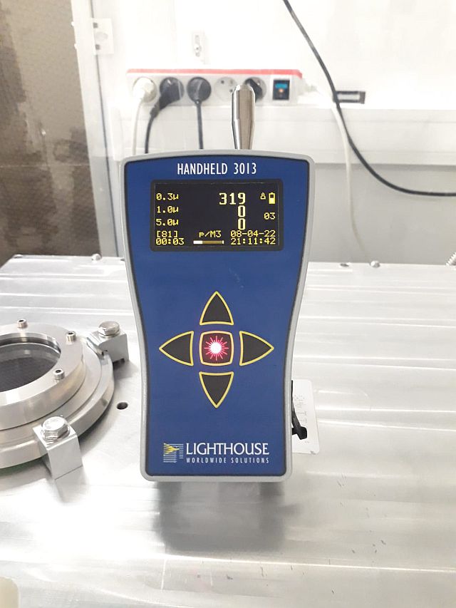
Dust measurement done today on top of the SBox average 10min
| Manar Amer wrote: |
|
The dust meter cap was cleaned using Alcohol, and using the filter white cap the dust count was (0 Av. 10 min)
After the dust counter was hand held in direct airflow, it counted (1581 p/m3 Av. 2 min).
I tested the count also in the SAS, and it counted twice the amount ~ 4500 p/m3
Note: discussion on the next steps to take for the airflow filtering !!!!!!!!
|
|
| Attachment 1: 20220408_DustMeasurement.jpg
|
 |